
Light route control member

a technology of light route control and light route, which is applied in the direction of instruments, polarising elements, optics, etc., can solve the problems of reducing the light blocking characteristic the range of use of the switchable light route control film, so as to achieve the effect of convenient us

Pending Publication Date: 2022-09-15
LG INNOTEK CO LTD
View PDF0 Cites 0 Cited by
  • Summary
  • Abstract
  • Description
  • Claims
  • Application Information

AI Technical Summary

Benefits of technology

The patent text describes a light route control member that can be connected to a display device to control the display. The control member is portable and can be easily detached from the display. It can control the sizes of different parts to maintain its performance even at low voltages. The light conversion unit has a multi-layer structure and can be driven in different ways to suit various usage environments. Additionally, the control member can control viewing angles in four directions instead of two by varying the extending directions of the light conversion unit.

Problems solved by technology

However, since the switchable light-shielding film is fixed to a specific display device, there is a problem in that the range of use of the switchable light-shielding film is limited.
In addition, when the portable switchable light-shielding film is applied, there is a problem in that the light blocking characteristic of the switchable light-shielding film is reduced because the voltage applied to the power connection unit is low.

Method used


Image

  • Light route control member
  • Light route control member
  • Light route control member

Examples


Embodiment Construction

[0026]Hereinafter, embodiments of the present invention will be described in detail with reference to the accompanying drawings. However, the spirit and scope of the present invention is not limited to a part of the embodiments described, and may be implemented in various other forms, and within the spirit and scope of the present invention, one or more of the elements of the embodiments may be selectively combined and replaced.

[0027]In addition, unless expressly otherwise defined and described, the terms used in the embodiments of the present invention (including technical and scientific terms) may be construed the same meaning as commonly understood by one of ordinary skill in the art to which this invention belongs, and the terms such as those defined in commonly used dictionaries may be interpreted as having a meaning that is consistent with their meaning in the context of the relevant art.

[0028]In addition, the terms used in the embodiments of the present invention are for desc...


PUM

PropertyMeasurementUnit
heightaaaaaaaaaa
driving voltageaaaaaaaaaa
widthaaaaaaaaaa

Abstract

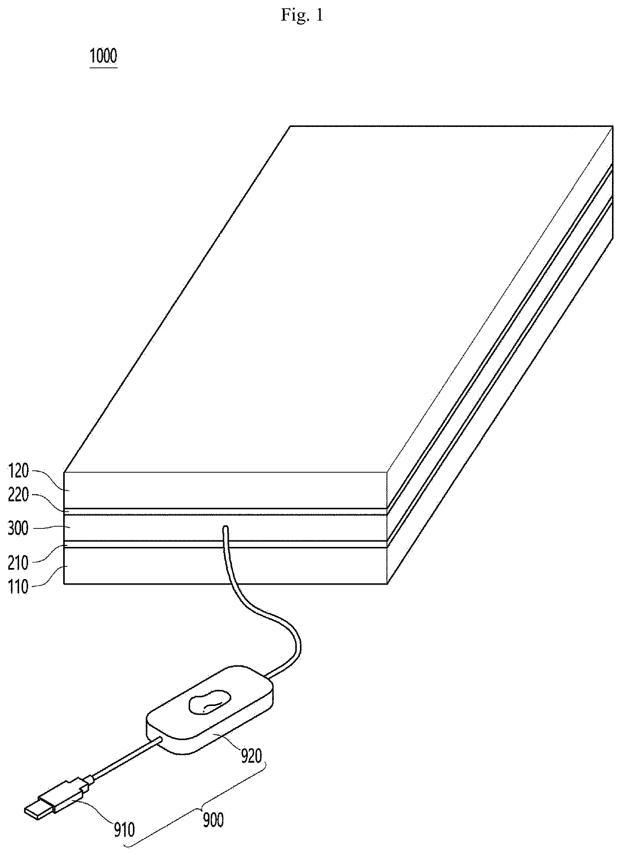
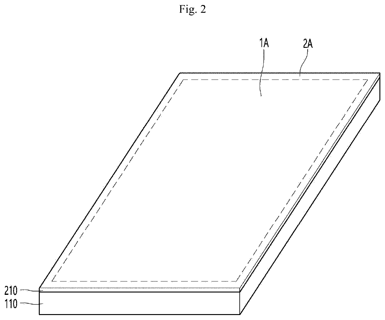
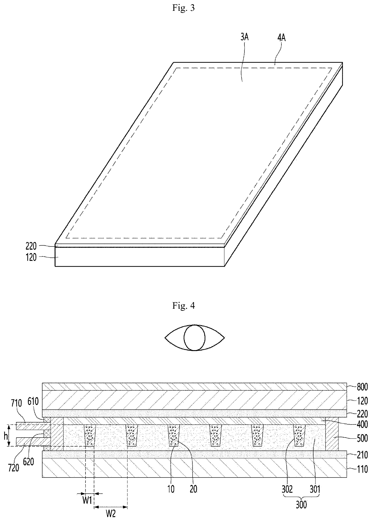
A light path control member according to an embodiment comprises: a first substrate; a first electrode disposed on the first substrate; a second substrate disposed on the first substrate; a second electrode disposed below the second substrate; a light conversion unit disposed between the first electrode and the second electrode; and a power supply unit connected to the first electrode and the second electrode, wherein the light conversion unit includes a partition wall part and a receiving part that are alternately arranged, the receiving part has a light transmittance that changes in response to the application of a voltage, the receiving part includes a dispersion liquid and a plurality of light absorbing particles dispersed in the dispersion liquid, the height of the receiving part is 15 μm to 25 μm, the width of the receiving part is 1.5 μm to 2.5 μm, and the power supply unit includes a power connection part connecting an external power source and the light conversion unit, and a power switch part for turning on / off the transmission of the voltage.

Description

TECHNICAL FIELD[0001]An embodiment relates to a light route control member capable of controlling a viewing angle of emitted light.BACKGROUND ART[0002]A light-shielding film shields transmitting of light from a light source, and is attached to a front surface of a display panel which is a display device used for a mobile phone, a notebook, a tablet PC, a vehicle navigation device, a vehicle touch, etc., so that the light-shielding film adjusts a viewing angle of light according to an incident angle of light to express a clear image quality at a viewing angle needed by a user when the display transmits a screen.[0003]In addition, the light-shielding film may be used for the window of a vehicle, building or the like to shield outside light partially to prevent glare, or to prevent the inside from being visible from the outside.[0004]That is, the light-shielding film may be a light route control member that controls a movement path of light, block light in a specific direction, and tra...

Claims


Application Information

Patent Timeline
Patent Type & Authority Applications(United States)
IPC IPC(8): G02F1/167G02F1/1685G02F1/1679G02F1/1676
CPCG02F1/167G02F1/1685G02F1/1679G02F1/1676G02F1/1675G02F1/1347H10K59/50G02B5/30G02B26/08G02F1/1323G02F1/1681
Inventor HAN, YOUNG JULEE, IN HAEKIM, BYUNG SOOK
Owner LG INNOTEK CO LTD
Learn More