Supercharge Your Innovation With Domain-Expert AI Agents!

Floor assemblies and methods

a technology for floor assemblies and methods, applied in the direction of aircraft accessories, construction, building components, etc., can solve the problems of not being able or practical to manually remove liquid from the floor, not being cleaned regularly, and floor liquid may be subject to spillage or leakag

Active Publication Date: 2022-09-22
THE BOEING CO
View PDF10 Cites 0 Cited by
  • Summary
  • Abstract
  • Description
  • Claims
  • Application Information

AI Technical Summary

Benefits of technology

The present patent provides a floor assembly for enclosed spaces, including a grid, pan, and surround member. The pan is placed beneath the grid and has an array of openings to allow liquid to pass through. The GRID is positioned above the pan and is supported by the frame. The surround member is positioned above the frame and out of contact with the grid. This design allows for proper drainage and can be easily installed. The technical effect of this floor assembly is that it provides a proper and efficient drainage system for enclosed spaces, while being easily installed and maintained.

Problems solved by technology

In various environments, floors may be subject to spillage or leakage of liquids.
It may not be possible or practical to manually remove the liquid from the floor in as short a time as may be desired.
However, during a flight, they may not be cleaned regularly.
Consequently, the dryness of lavatory floors onboard an aircraft may be compromised, particularly during flights.
Further, maintenance of floor assemblies used to drain or remove liquid from the floor may be difficult or inconvenient, for example in the close quarters generally found in aircraft lavatories.

Method used


Image

  • Floor assemblies and methods
  • Floor assemblies and methods
  • Floor assemblies and methods

Examples


Embodiment Construction

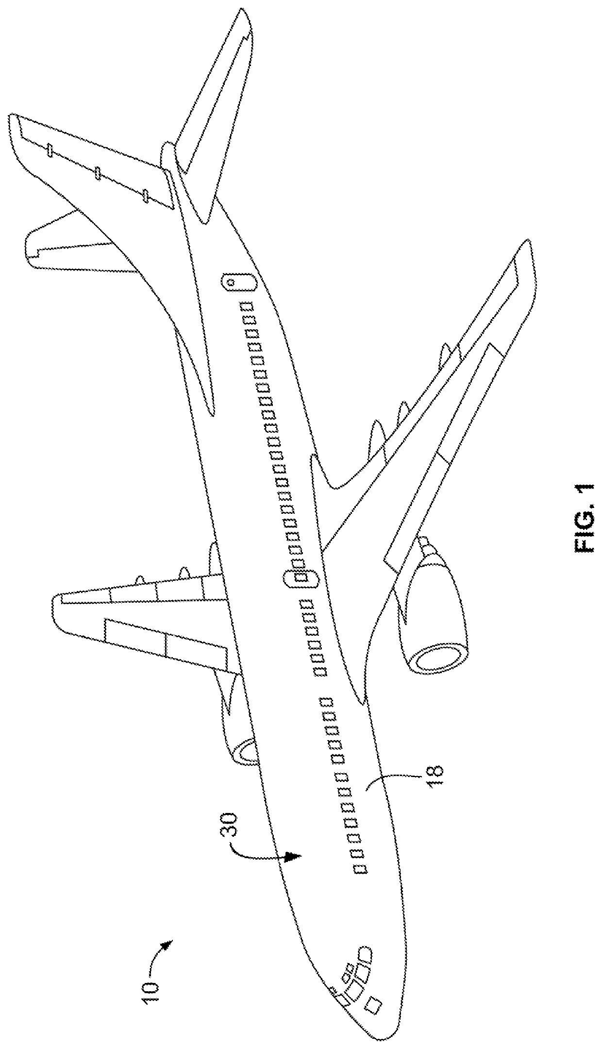
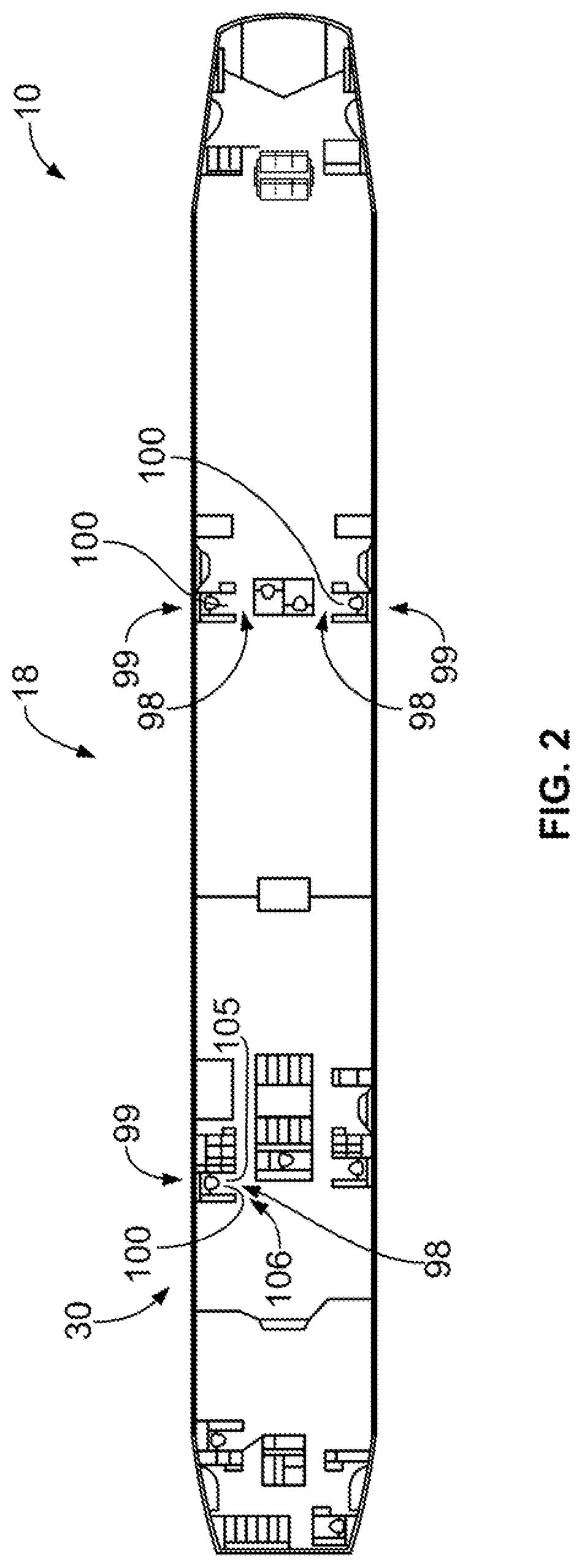
[0018]Embodiments of the present disclosure provide for providing a dry floor, such as a lavatory floor. Embodiments may be used in various settings, such as within a lavatory of a vehicle, a public washroom in a building, a laboratory, and / or the like. Examples of vehicles for various embodiments include aircraft, ships, or ground-based vehicles, such as buses or trains.

[0019]Various embodiments provide a method and a floor assembly that can have improved ease of use, including maintenance and replacement of components. Various embodiments can effectively and efficiently provide a dry lavatory floor having improved convenience of service and maintenance onboard an aircraft, particularly during a flight.

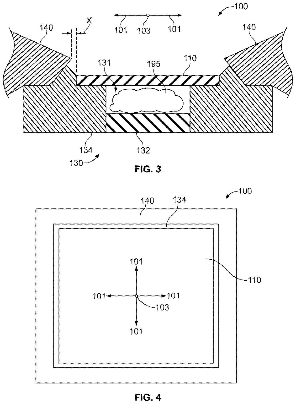
[0020]Various embodiments of the present disclosure can provide a floor assembly (e.g., a dry floor assembly) for removing liquids from a floor or walking surface. Various embodiments may provide a grid or structure located above a removable absorbent pad is easily and conveniently r...


PUM


Abstract

A floor assembly is provided. The floor assembly is configured to form or be positioned on a floor of an enclosed space. The floor assembly includes a grid, a pan, and a surround member. The grid has an array of openings configured to allow passage of liquid. The pan is disposed beneath the grid and defines a cavity. The pan includes a pan floor and a frame. The frame is disposed laterally outward of the pan floor and supports the grid. The surround member is supported by the frame. The surround member is disposed laterally outward of the grid, and the surround member and grid do not overlap.

Description

RELATED APPLICATIONS[0001]This application is a continuation of U.S. application Ser. No. 16 / 895,937, entitled “Floor Assemblies and Methods,” filed Jun. 8, 2020, which is hereby incorporated by reference in its entirety.[0002]FIELD OF THE DISCLOSURE[0003]Embodiments of the present disclosure generally relate to assemblies and methods for providing a floor for collection and / or removal of liquid, such as a lavatory floor within a commercial aircraft.BACKGROUND OF THE DISCLOSURE[0004]In various environments, floors may be subject to spillage or leakage of liquids. It may not be possible or practical to manually remove the liquid from the floor in as short a time as may be desired. For example, commercial aircraft are used to transport passengers between various locations. During a flight—particularly a trans-oceanic or other long haul flight—passengers are typically confined within certain areas (for example, cabins) of an aircraft. Various individuals (such as passengers, pilots, fl...

Claims


Application Information

Patent Timeline
Patent Type & Authority Applications(United States)
IPC IPC(8): E04B5/48B64C1/18
CPCE04B5/48B64C1/18B64D11/02
Inventor CHILDRESS, JAMIE J.
Owner THE BOEING CO
Features
  • R&D
  • Intellectual Property
  • Life Sciences
  • Materials
  • Tech Scout
  • Unparalleled Data Quality
  • Higher Quality Content
  • 60% Fewer Hallucinations
Learn More