Load control device

a control device and load technology, applied in the direction of measurement devices, emergency protective circuit arrangements, instruments, etc., can solve the problems of large delay between the actual detection the occurrence of the half-on failure inside the semiconductor switch, and the resistance of the failed semiconductor switch may generate a large amount of heat, so as to achieve the effect of preventing overheating

Pending Publication Date: 2022-09-29
YAZAKI CORP
View PDF4 Cites 0 Cited by
  • Summary
  • Abstract
  • Description
  • Claims
  • Application Information

AI Technical Summary

Benefits of technology

[0010]The present invention has been made in view of the above circumstances, and an object of the present invention is to p...

Problems solved by technology

In the load control device as described above, there is a concern that a half-on failure may occur.
When the half-on failure occurs, a large amount of heat may be generated by the resistance inside the failed semiconductor switch due to an influence of a large current that continues to flow through the load.
However, since the temperature is detected outside the semiconductor switch, it is expected that a delay of the time from occurrence of the half-on failure inside the semiconductor switch to actual detection of the half-on failure is large due to a dela...

Method used


Image

  • Load control device
  • Load control device
  • Load control device

Examples


first embodiment

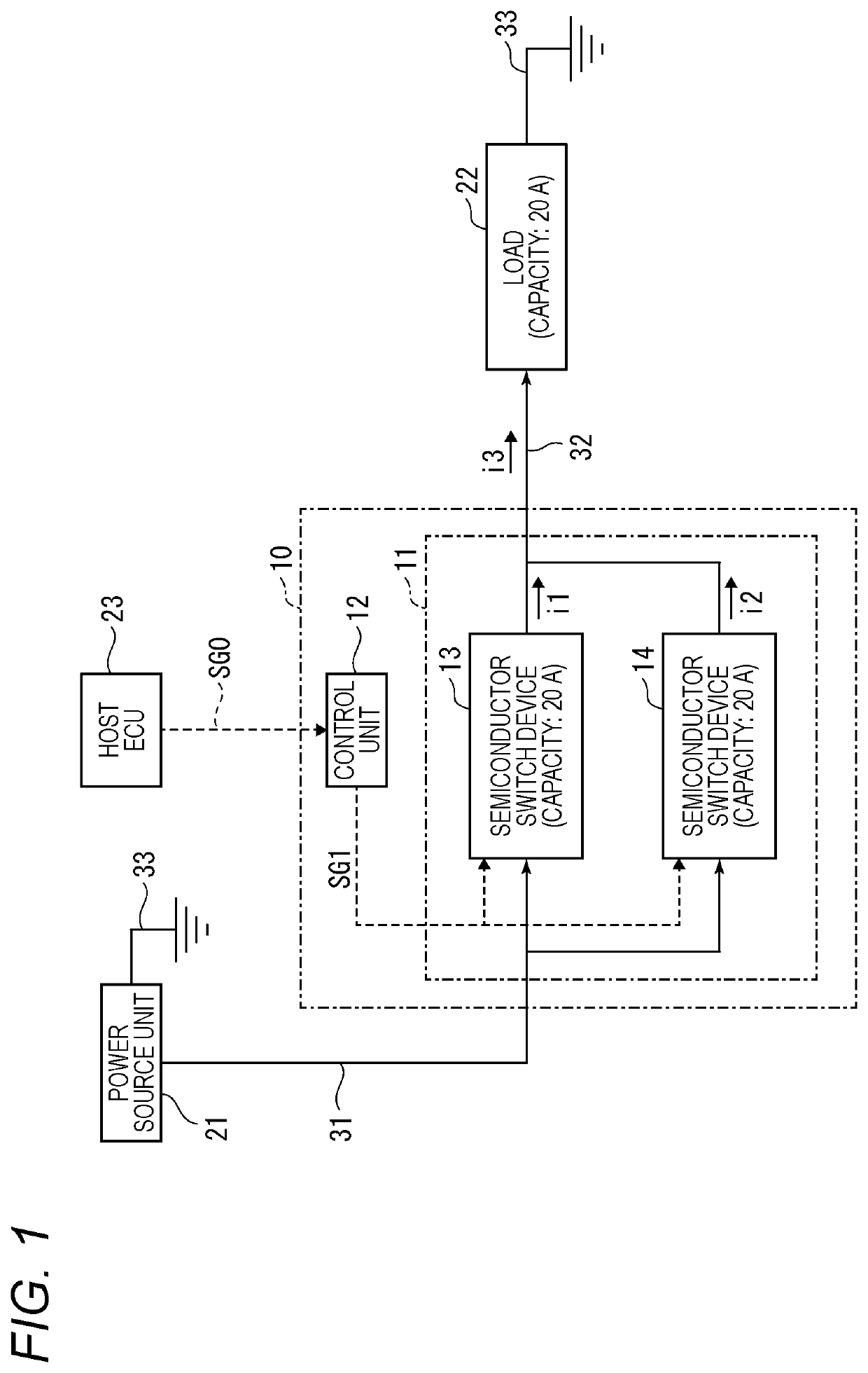
[0025]FIG. 1 is a block diagram showing a configuration example of a load control device 10 according to a first embodiment of the present invention.

[0026]The load control device 10 shown in FIG. 1 is used to perform ON-OFF control of energization when power output from a power source unit 21 is supplied to a load 22. Actually, the power source unit 21 corresponds to a power source such as an in-vehicle battery, and the load 22 corresponds to various electrical components mounted on a vehicle, for example, a lamp, a heater, an electric motor, an ECU, and the like.

[0027]In the example shown in FIG. 1, it is assumed that a current capacity of the load 22 connected to an output side of the load control device 10 is 20 [A].

[0028]A power source input side of the load control device 10 is connected to the power source unit 21 via a power line 31. The output side of the load control device 10 is connected to one end of the load 22 via a power line 32, and the other end of the load 22 is co...

second embodiment

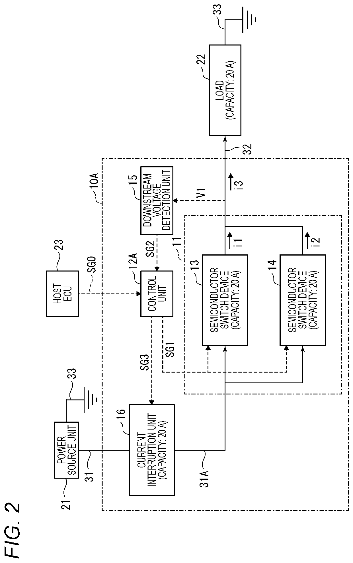
[0048]FIG. 2 is a block diagram showing a configuration example of a load control device 10A according to a second embodiment of the present invention. Similarly to the load control device 10 according to the first embodiment, the load control device 10A shown in FIG. 2 is used to perform the ON-OFF control of the energization when the power output from the power source unit 21 is supplied to the load 22. The load control device 10A is designed on the assumption that the current capacity of the load 22 connected to an output side of the load control device 10A is 20 [A].

[0049]Similarly to the load control device 10, the load control device 10A shown in FIG. 2 includes the energization circuit unit 11 and a control unit 12A. The load control device 10A further includes a downstream voltage detection unit 15 and a current interruption unit 16.

[0050]As in the first embodiment, a power source input side of the load control device 10A is connected to the power source unit 21 via the powe...


PUM


Abstract

A load control device includes an energization circuit unit connected between a power source and a load and configured to switch ON and OFF of energization of the load, a failure detection unit connected to a downstream side of the energization circuit unit, a current interruption unit connected to an upstream side of the energization circuit unit and configured to interrupt supply of current of the power source to the energization circuit unit based on an input from the failure detection unit, and a control unit configured to supply an ON-OFF control signal to the energization circuit unit. The energization circuit unit includes a first semiconductor switch and a second semiconductor switch which are connected in parallel to each other The control unit supplies a common ON-OFF control signal to the first semiconductor switch and the second semiconductor switch.

Description

CROSS-REFERENCE TO RELATED APPLICATIONS[0001]This application is based on and claims priority under 35 USC 119 from Japanese Patent Application No. 2021-050051 filed on Mar. 24, 2021, the contents of which are incorporated herein by reference.TECHNICAL FIELD[0002]The present invention relates to a load control device, and more particularly, to a load control device that controls energization of a load using a semiconductor switch.BACKGROUND ART[0003]For example, when power is supplied from a power source such as a battery to loads such as various electrical components on a vehicle, ON and OFF of power supply from the power source to the loads may be controlled using a semiconductor switch.[0004]In the load control device as described above, there is a concern that a half-on failure may occur. In the half-on failure, the semiconductor switch is in a conductive state (ON state) while having a certain resistance value inside the semiconductor switch and the state is not switched as it ...

Claims


Application Information

Patent Timeline
IPC IPC(8): H02H7/20H02H1/00
CPCH02H7/20H02H1/0007H02H7/1203H02M1/32G01R31/3277H02H3/202
Inventor KAMIYA, YUKIO
Owner YAZAKI CORP
Why Eureka
Try Eureka