Self-propelled ground milling machine and method for operating a ground milling machine in an emergency mode of operation

a ground milling machine and self-propelled technology, which is applied in the maintenance of roads, roads, roads, etc., can solve the problems of comparatively low power consumption, small and compact structure of hydraulic pumps,

Pending Publication Date: 2022-10-06
BOMAG
View PDF0 Cites 0 Cited by
  • Summary
  • Abstract
  • Description
  • Claims
  • Application Information

AI Technical Summary

Problems solved by technology

This means that the emergency hydraulic pump can be configured to be small and com...

Method used


Image

  • Self-propelled ground milling machine and method for operating a ground milling machine in an emergency mode of operation
  • Self-propelled ground milling machine and method for operating a ground milling machine in an emergency mode of operation
  • Self-propelled ground milling machine and method for operating a ground milling machine in an emergency mode of operation

Examples


Embodiment Construction

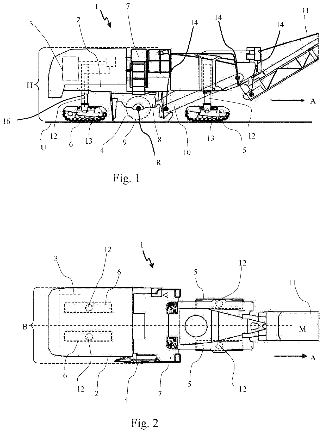
[0028]FIG. 1 shows a side view of a ground milling machine 1, more specifically the right side of the machine relative to the forward direction A. The essential elements of the ground milling machine 1 are a machine frame 2, a primary drive unit 3, preferably a diesel internal combustion engine, a ground milling device 4, front travel units 5, rear travel units 6 and an operator platform 7. The ground milling device comprises a milling drum box 8, inside which a milling drum 9 (indicated by dashed lines in FIG. 1) is provided. The latter may comprise a hollow-cylindrical support tube with a plurality of milling tools arranged on its outer circumferential surface. The milling drum 9 rotates about a horizontal rotation axis R extending transversely to the forward direction A. In milling operation, the milling drum 9 engages the ground U and mills off ground material. The resulting milled material is collected in the milling drum box 8 and can then be loaded via transport devices 10 an...


PUM


Abstract

The present invention relates to a self-propelled ground milling machine and a method for operating a ground milling machine in an emergency mode of operation.

Description

CROSS-REFERENCE TO RELATED APPLICATIONS[0001]The present application claims priority under 35 U.S.C. § 119 of German Patent Application No. 10 2021 001 759.5, filed Apr. 6, 2021 and German Patent Application No. 10 2021 118 784.2, filed Jul. 20, 2021, the disclosures of which are hereby incorporated herein by reference in their entireties.FIELD OF THE INVENTION[0002]The present invention relates to a ground milling machine and a method for operating a ground milling machine in an emergency mode of operation.BACKGROUND OF THE INVENTION[0003]A generic ground milling machine is self-propelled and comprises a machine frame, an operator platform, a primary drive unit with which the drive energy required for regular operation of the ground milling machine is provided, a ground milling device with a milling drum arranged within a milling drum box and rotatable about a rotation axis, and front and rear travel units, wherein at least one of the front and / or the rear travel units is connected...

Claims


Application Information

Patent Timeline
IPC IPC(8): E01C23/088
CPCE01C23/088E01C23/127
Inventor ZEHBE, JENS-MARTIN
Owner BOMAG
Why Eureka
Try Eureka