
Anchor chair

a technology for anchoring chairs and elongated foundations, applied in the field of anchor chairs, can solve the problems of reducing efficiency, increasing the risk of mistakes, and the end of the elongated foundation element being exposed to inacceptable forces

Pending Publication Date: 2022-10-06
PROFERRO NV
View PDF0 Cites 0 Cited by
  • Summary
  • Abstract
  • Description
  • Claims
  • Application Information

AI Technical Summary

Benefits of technology

This patent describes an improved design for installing an anchor chair for use with an elongated foundation element. The slot-shaped opening in the anchor chair allows for a secure attachment to the foundation element at various angles. The front outer surface of the anchor chair extends perpendicular to the axis of the foundation element, ensuring efficient transmission of pulling force. The use of a single type of anchor chair for different application angles reduces the likelihood of installing the wrong one. Overall, this design provides a simple and effective way to install an anchor chair for use with elongated foundation elements.

Problems solved by technology

This requires the use of different types of anchor chairs, each having an abutment surface at a different angle, what reduces the efficiency as all necessary types of anchor chairs must be present on the construction site.
It also increases the risk of mistakes, wherein the correct type of anchor chair is not used, and the end of the elongated foundation element is exposed to unacceptable forces and / or deformations when attaching the anchor nut against the anchor chair.
To resist the desired pulling force of the elongated foundation element without unwanted deformations, typically a relative thick and strong plate material must be used, which is disadvantageous for manufacturing such an anchor chair, as this for example complicates sawing operations, pleating operations, boring operations, and the like, that are necessary for manufacturing the anchor chair.
After arranging the anchor nut, it is difficult to verify if the side facing the wall of the anchor chair leans correctly against the wall for transmitting the pulling force on the wall, whereby unacceptable deformations of the wall and / or the anchor chair may occur which remain hidden from view as they are completely covered by the anchor chair.

Method used


Image

  • Anchor chair
  • Anchor chair
  • Anchor chair

Examples


Embodiment Construction

)

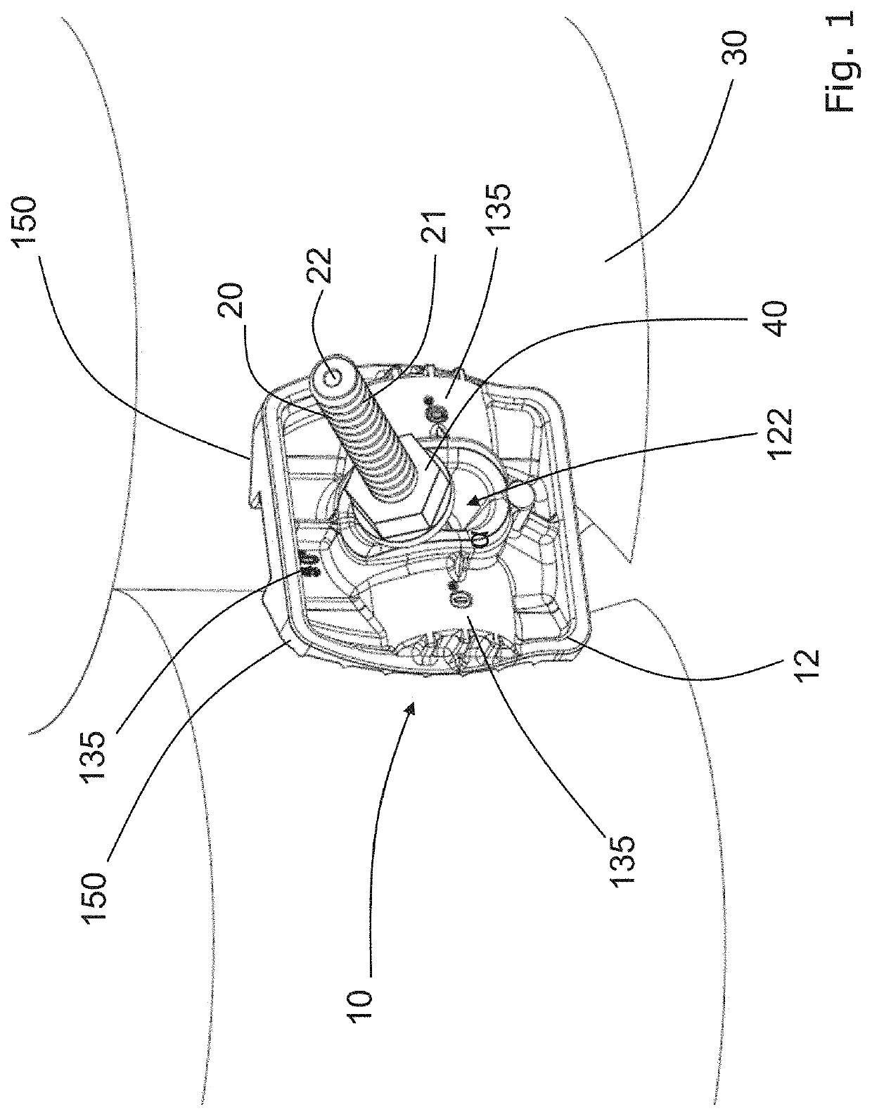
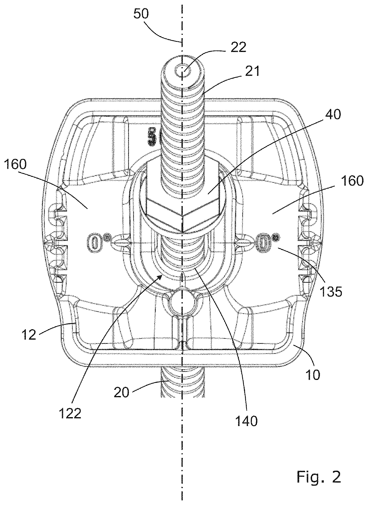
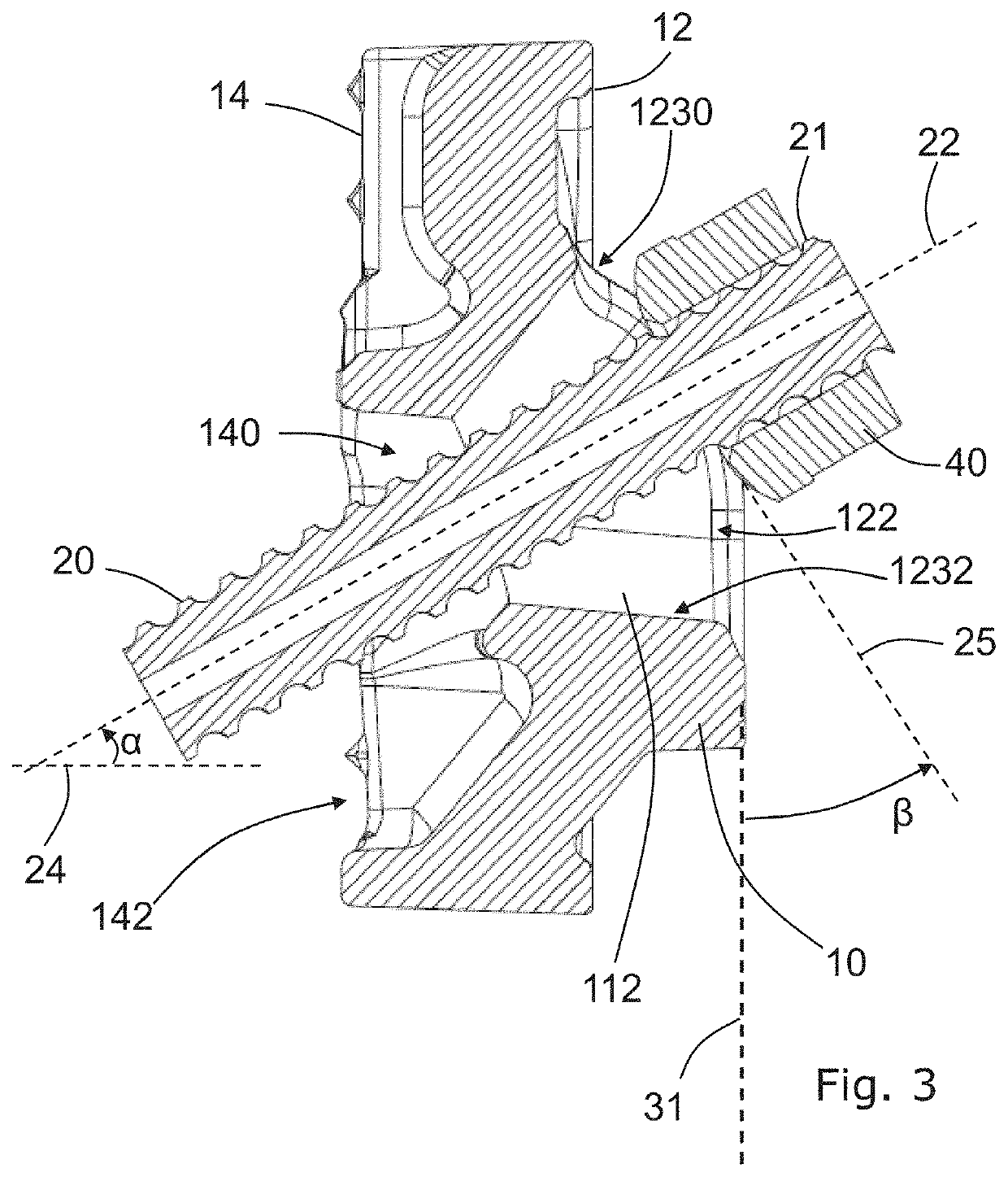
[0055]An anchor chair 10 according to the present invention, in attached state to a wall 30, in this case a secant pile wall, is shown in FIG. 1, FIG. 2 and FIG. 3. FIG. 1 shows a perspective view of the anchor chair 10 and FIG. 2 shows a front view of the anchor chair 10. FIG. 3 is a cross section of the anchor chair 10 in attached state to the wall 30, seen according to a plane 50 (see FIG. 2), which plane 50 is perpendicular to the wall 30 and comprising the elongated foundation element 20, more particular its axis 22.

[0056]The anchor chair 10 is configured to transmit a pulling force from an elongated foundation element 20 to the wall 30. A fastening element 40, for example a nut is screwed on the outer end 21 of the elongated foundation element 20 extending from the wall 30 through the anchor chair 10. As such, the pulling force from the elongated foundation element 20 is transmitted to the wall 30 via the fastening element 40 and the anchor chair 10.

[0057]More details of the ...


PUM


Abstract

An anchor chair is configured for transmitting a pulling force from an elongated foundation element to a wall. The anchor chair includes a passage for the elongated foundation element, and a cavity between a first opening located on a first side of the anchor chair, which first side is facing away from the wall in attached state, and a second opening located on an opposite side of the anchor chair, which opposite side is facing the wall in attached state and which opposite side defines in attached state a contact area of the anchor chair to contact the wall. The first opening is a slot-shaped opening having two long sides and two short sides. In an attached state, the long sides of the slot-shaped opening of the anchor chair are oriented parallel to a plane perpendicular to the wall.

Description

FIELD OF THE INVENTION[0001]The technical field concerns an anchor chair, also named anchor, as well as a composition comprising an anchor chair, for anchoring an elongated foundation element to a wall, wherein the anchor chair transmits a pulling force from an elongated foundation element to a wall.BACKGROUND OF THE INVENTION[0002]The invention concerns anchor chairs that are used, inter alia, for grout anchors, screw anchors, screw injection anchors and anchor partitions as anchorage elements for walls such as for example construction pit walls, dam walls, walls for a quay construction, walls for basement floors, tunnel walls, and such walls. In this case, such an anchor chair transmits a pulling force from an elongated foundation element to such a wall. In this case, the elongated foundation element is inserted, for example through the wall in the surrounding soil or the surrounding rock.[0003]A known anchor chair for anchoring a wall is for example described in U.S. Pat. No. 3,9...

Claims


Application Information

Patent Timeline
IPC IPC(8): E02D5/76
CPCE02D5/76E02D17/08E02D5/74E04H12/2284E04H12/2276
Inventor DESCAMPS, RIKCORNILLIE, CHRISTIAN
Owner PROFERRO NV
Learn More