Chip-type current fuse

a current fuse and chip-type technology, applied in the direction of thermally actuated switches, electric switches, electrical equipment, etc., can solve the problems of reducing the thermal capacity of the fuse element and the decrease of pulse resistance, and achieve the effect of stabilizing timing

Pending Publication Date: 2022-10-06
KOA CORP
View PDF31 Cites 0 Cited by
  • Summary
  • Abstract
  • Description
  • Claims
  • Application Information

AI Technical Summary

Benefits of technology

[0015]In the chip-type current fuse according to the present invention, the inclined linear portion formed between the first linear portion and the second linear portion is connected at an acute angle to each of the linear portions. This enables stabilization of timing when the fuse element melts.

Problems solved by technology

Where the fuse element is formed between the pair of front electrodes in a linear fashion, a shorter distance between the front electrodes with reduction in size of the chip-type current fuse causes a reduced thermal capacity of the fuse element, which in turn results in a decrease in pulse resistance.

Method used


Image

  • Chip-type current fuse
  • Chip-type current fuse
  • Chip-type current fuse

Examples


Embodiment Construction

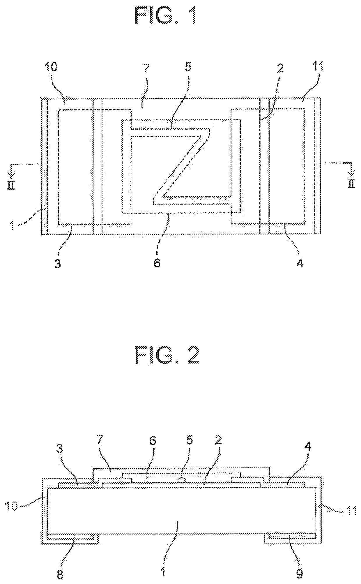
[0022]Embodiments according to the invention will now be described with reference to the accompanying drawings. FIG. 1 is a plan view of a chip-type current fuse according to example embodiments of the present invention. FIG. 2 is a sectional view taken along line II-II of FIG. 1.

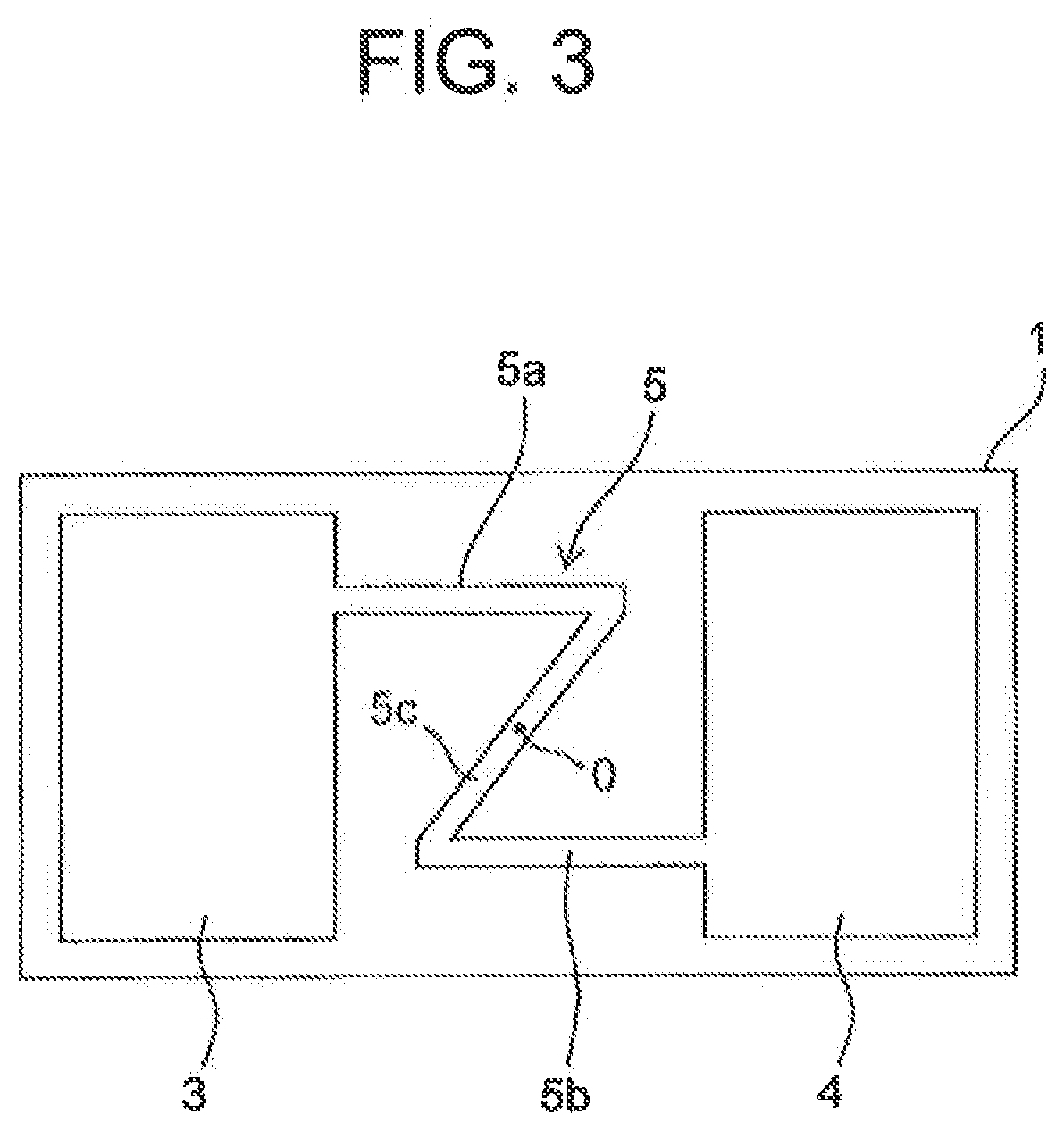
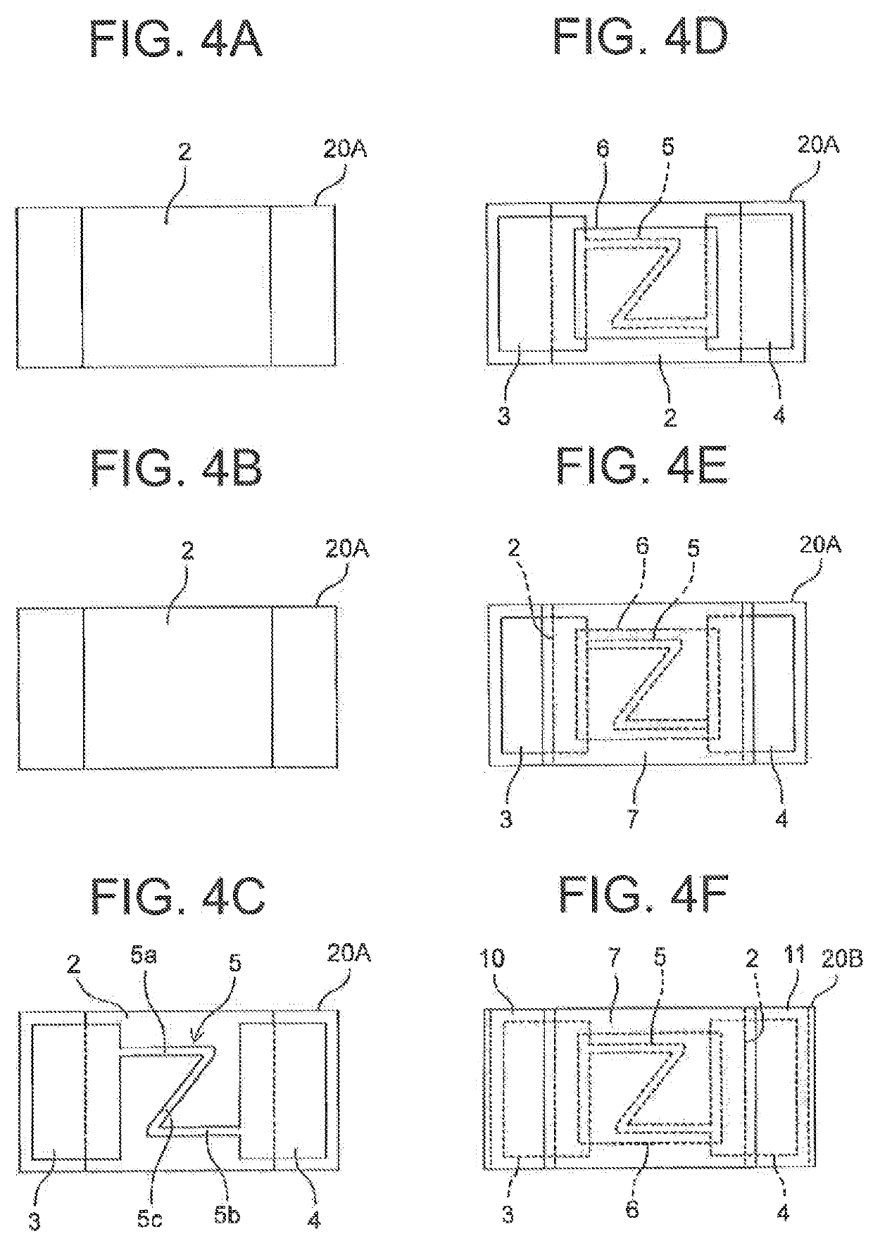
[0023]As illustrated in FIGS. 1 and 2, the chip-type current fuse according to the example embodiments mainly includes: an insulating substrate 1 of a rectangular solid shape; a thermal storage layer 2 that is formed on a region of the front face of the insulating substrate 1 other than both longitudinal end portions thereof; a first front electrode 3 and a second front electrode 4 that are formed on the both longitudinal end portions of the front face of the insulating substrate 1 to overlap partially the thermal storage layer 2; a fuse element 5 that is formed on the thermal storage layer 2 to provide continuity between the first front electrode 3 and the second front electrode 4; an inner protective laye...


PUM

PropertyMeasurementUnit
angleaaaaaaaaaa
distanceaaaaaaaaaa
areaaaaaaaaaaa

Abstract

The chip-type current fuse is configured to include a fuse element 5 formed between a first front electrode 3 and a second front electrode 4. The fuse element 5 includes: a first linear portion 5a that has an end connected to the first front electrode 3 and extends in a direction toward the second front electrode 4; a second linear portion 5b that has an end connected to the second front electrode 4 and extends in parallel to the first linear portion 5a in a direction toward the first front electrode 3; and an inclined linear portion 5c that links the first linear portion 5a and the second linear portion 5b to each other. The inclined linear portion 5c is connected at an acute angle to each of the first linear portion 5a and the second linear portion 5b.

Description

TECHNICAL FIELD[0001]The present invention relates to a surface mounting chip-type current fuse.BACKGROUND ART[0002]A chip-type current fuse mainly includes: an insulating substrate of a rectangular solid shape; a pair of front electrodes that are respectively formed on both longitudinal end portions of the front surface of the insulating substrate; a fuse element that is formed between the pair of front electrodes; a protective layer that covers the fuse element; a pair of back electrodes that are formed on both longitudinal end portions of the back face of the insulating substrate; a pair of end electrodes that are formed on both longitudinal end faces of the insulating substrate and each provides connection between the corresponding front electrode and the corresponding back electrode; and the like.[0003]In the chip-type current fuse configured in this way, if a predetermined overcurrent flows between a pair of front electrodes, the current is concentrated on the fuse element, so...

Claims


Application Information

Patent Timeline
Patent Type & Authority Applications(United States)
IPC IPC(8): H01H37/76
CPCH01H37/761H01H85/046H01H85/055H01H85/08
Inventor ICHIKAWA, HIROSHIOGUCHI, TOMONORIKARASAWA, ATSUSHI
Owner KOA CORP
Why Eureka
Try Eureka