Automatically retracting safety needle assembly

a safety needle and automatic retracting technology, which is applied in the field of safety needle assemblies, can solve the problems of contamination and needlestick injury of still extended and used needles, difficulty in fully pushing the plunger all the way, and inability to fully depress the plunger. to prevent proximal movement

Pending Publication Date: 2022-10-13
DALI MEDICAL DEVICES
View PDF3 Cites 0 Cited by
  • Summary
  • Abstract
  • Description
  • Claims
  • Application Information

AI Technical Summary

Benefits of technology

[0005]In accordance with one aspect of the present invention, there is thus provided an automatically retracting safety needle assembly. The assembly has a distal end and a proximal end. The assembly includes a housing, which includes an internal housing (IH), which includes an inner tube concentric with an outer tube, and a base wall situated at the distal end of the IH. The assembly further includes a moving sleeve (MOS), disposed within the IH. The MOS includes a flange wall, at the proximal end thereof, and the MOS is axially movable. The assembly further includes a biasing element (BE), disposed within the IH. The BE is supported at its distal end by the base wall of the IH and is supported at its proximal end by the flange wall of the MOS. The BE biases the MOS to the proximal direction. The assembly further includes a syringe, disposed in and movable axially within the inner tube of the IH, and coupled to the MOS. The syringe includes: a syringe chamber, containing an injectant substance; a plunger rod, slidably advanceable within the syringe chamber; a plunger stopper, disposed on the distal end of the plunger rod; and a needle, extending from a distal end of the syringe. The assembly further includes an activation fork (AF), disposed within the IH. The AF includes an end member at a proximal end thereof, and at least one guiding arm extending distally from the end member and aligned axially. The guiding arm is coupled with the IH and the MOS so as to prevent proximal motion of the MOS when the assembly is in a non-deployment state. The assembly further includes a retraction mechanism, configured to automatically retract the needle upon completion of injection. The assembly is configured to be deployed for injection by inserting the needle into an injection site, and advancing the plunger rod and the AF axially in the distal direction with respect to the IH, urging the plunger stopper to advance distally within the syringe chamber to expel the injectant substance therefrom through the needle, the plunger rod advancing until the guiding arm of the AF allows movement of the MOS, where the distal advancement of the plunger rod is substantially constant without an abrupt increase in resistive force to overcome for activating the retraction mechanism, allowing for safe disposal of the needle assembly with the needle retracted within the housing. The assembly may further include an indicator, configured to provide an indication of completion of the injection. The assembly may further include a removable needle guard, configured to cover the distal end of the needle when the needle assembly is in the non-deployment state, and to be removed before the injection. The housing may further include an external housing, where the internal housing is fixedly coupled to the external housing at the proximal end thereof. The movable sleeve (MOS) may be a rotating sleeve (ROS), which includes at least one extending arm, extending distally from the flange wall. The ROS further includes a guiding slot on the extending arm, the guiding slot including: a helical-shaped slot portion at the proximal edge of the guiding slot; an elongated straight slot portion distal of the helical-shaped slot portion; and an extension slot portion extending from the straight slot portion. The ROS further includes at least one notched flange, protruding radially outwards from the flange wall, the notched flange including a wide notch. The ROS further includes at least one holding snap, projecting proximally from the edge of the flange wall. The inner tube of the IH may further include at least one direction protrusion positioned inside the guiding slot. The guiding arm of the AF may be coupled with the IH and the ROS by insertion into guiding ribs of the outer tube of the IH, and by insertion into the wide notch of the notched flange of the ROS. The syringe may be coupled to the ROS via the holding snap of the ROS, preventing axial motion of the syringe flange relative to the ROS when the assembly is in the non-deployment state. The flange wall of the ROS may include at least one arc-shaped opening, and the inner tube of the IH may further includes at least one orienting protrusion, configured to prevent rotation of the syringe, where the orienting protrusion is positioned through the arc-shaped opening of the flange wall of the ROS. After the needle is inserted into the injection site, the plunger may advance until the guiding arms of the AF passes through the wide notch of the notched flange of the ROS, allowing for rotation of the ROS inside the end member of the AF, and allowing the biasing force of the BE to move the ROS in the proximal direction, resulting in the directing protrusion urging rotation of the ROS, until the directing protrusion is guided from the helical slot into the straight slot of the guiding slot of the ROS, allowing for further axial movement of the ROS in the proximal direction. The inner tube of the IH may further include at least one locking snap, where further axial movement of the ROS in the proximal direction causes the locking snap of the IH to engage the distal end of the guiding slot and to bend radially to allow continuation of the ROS axial movement, with reciprocal axial movement of the syringe so as to proximally retract the syringe chamber with the needle into the housing, until the distal end of the guiding slot engages the directing protrusion of the IH, and the distal end of the extended arm of the ROS is positioned between the locking snap and the directing protrusion of the IH, such that the directing protrusion prevents further proximal axial movement of the ROS and the syringe, and the locking snap prevents further distal axial movement of the ROS and the syringe, while the alignment of the guiding arm of the AF relative to the notched flange of the ROS prevents detachment of the AF. The movable sleeve (MOS) may be a locking sleeve (LOS), which includes at least one extending arm, extending distally from the flange wall. The LOS further includes a respective gripping snap, disposed on the extending arm, the gripping snap including an extending protrusion with a radially facing slope at the distal end thereof. The LOS further includes at least one holding snap, projecting proximally from the edge of the flange wall. The AF may further include an activation opening, disposed on the guiding arm, where the the guiding arm of the AF is positioned between the gripping snap of the LOS and the IH, such that the guiding arm prevents the gripping snap from deflecting radially, and prevents proximal movement of the LOS, when the assembly is in a non-deployment position. The LOS may further include a respective locking snap, disposed on the extending arm, the locking snap including an extending protrusion with a deflecting slope at the distal end thereof. The LOS may further include at least one LOS stopping protrusion, extending distally from the flange wall. The AF may further include a locking opening, disposed on the guiding arm of the AF. The IH may further include at least one IH stopping protrusion, extending radially inwards from the proximal inner portion of the outer tube. The gripping snap and the locking snap may be a single unified snap, and the activation opening and the locking opening may be a single unified opening. After the needle is inserted into the injection site, the plunger rod may be advanced until the activation opening of the guiding arm of the AF aligns with the gripping snap of the LOS, causing the gripping snap to deflect radially through the activation opening, allowing for proximal movement of the LOS due to the biasing force of the BE, with reciprocal axial movement of the syringe so as to proximally retract the syringe chamber with the needle into the housing, until the gripping snap passes the proximal end of the IH and returns to a non-deflected position. After the needle is inserted into the injection site, the plunger rod may be advanced until the locking opening of the guiding arm of the AF aligns with the locking snap of the LOS, causing the locking snap to deflect radially through the locking opening, during proximal movement of the LOS due to the biasing force of the BE, with reciprocal axial movement of the syringe so as to proximally retract the syringe chamber with the needle into the housing, until the locking snap passes the proximal end of the IH and returns to a non-deflected position, and the LOS stopping protrusion engages the IH stopping protrusion preventing further proximal movement of the LOS, and the locking snap restricts further distal movement of the LOS. The LOS may further include: a first locking window, disposed on the extending arm, distally of the gripping snap, a second locking window, disposed on the extending arm, distally of the first locking window, and at least one LOS stopping protrusion, disposed at the distal end of the extending arm, where the IH further includes at least one IH locking snap, disposed on a distally extending portion of the inner tube of the IH, the IH locking snap including a locking tooth at a proximal end thereof, where the LOS stopping protrusion is aligned angularly with the IH locking snap, and where the locking tooth of the IH locking snap is positioned within the first locking window, when the assembly is in a non-deployment position. The assembly may further include a removable needle guard, configured to cover the distal end of the needle when the assembly is in the non-deployment state, where the needle guard includes a proximal ring and a distal ring, radially encircling the outer circumferential surface of the needle guard, the diameter of the distal ring being smaller than the diameter of the proximal ring, and the assembly may further include an outer cap, positioned at the distal end of an external housing (EH) of the housing, the IH fixedly coupled to the EH at the proximal end thereof, the outer cap including: a cap body, a cap tube, proximal to the cap body, a connecting wall, separating the cap body from the cap tube, and at least one cap snap, disposed within the cap body and inclined radially inward, where the distal end of the cap snap is positioned proximal of the distal ring of the needle guard and the inner portion of the connecting wall is positioned distal of the proximal ring of the needle guard, such that the distal end of the cap snap engages with the distal ring so as to distally pull the needle guard with the outer cap upon distal pulling of the outer cap. The outer cap may further include at least one thick rib and at least one thin rib, extending longitudinally on the outer circumferential surface of the cap tube, the thick rib positioned orthogonal to the thin rib, where the outer cap is configured to cover the needle guard, where the cap tube is positioned within an EH distal tube of the EH and the cap body is positioned distally of a distal opening of the EH, and where the thick ribs and the thin ribs are correspondingly positioned within respective thick slots and thin slots on the EH distal tube, so as to orient the outer cap in relation to the EH. During proximal movement of the LOS due to the biasing force of the BE, with reciprocal axial movement of the syringe so as to proximally retract the syringe chamber with the needle into the housing, the stopping protrusion of the LOS may engage the distal end of the IH preventing further proximal movement of the LOS, and the locking snap of the IH may be aligned such that the locking tooth is positioned within the second locking window of the LOS, causing the locking snap to return to a non-deflected position, and the proximal end of the locking tooth may engage the proximal end of the second locking window, preventing further distal movement of the LOS and the syringe.
[0006]In accordance with another aspect of the present invention, there is thus provided a method for automatically retracting a safety needle assembly. The method includes the procedure of providing an automatically retracting safety needle assembly, the assembly having a distal end and a proximal end, the assembly including a housing, which includes an internal housing (IH), which includes an inner tube concentric with an outer tube, and a base wall situated at the distal end of the IH, the assembly further including a moving sleeve (MOS), disposed within the outer tube of the IH, the MOS including a flange wall, at the proximal end thereof, the MOS axially movable, the assembly further including a biasing element (BE), disposed within the IH, the BE supported at its distal end by the base wall of the IH and supported at its proximal end by the flange wall of the MOS, the BE biasing the MOS to the proximal direction, the assembly further including a syringe, disposed in and movable axially within the inner tube of the IH, and coupled to the MOS, the syringe including: a syringe chamber, containing an injectant substance; a plunger rod, slidably advanceable within the syringe chamber; a plunger stopper, disposed on the distal end of the plunger rod; and a needle, extending from a distal end of the syringe, the assembly further including an activation fork (AF), disposed within the IH, the AF including an end member at a proximal end thereof, and at least one guiding arm extending distally from the end member and aligned axially, the guiding arm coupled with the IH and the MOS so as to prevent proximal motion of the MOS when the assembly is in a non-deployment state, the assembly further including a retraction mechanism, configured to automatically retract the needle upon completion of injection. The method further includes the procedure of inserting the needle into an injection site. The method further includes the procedure of advancing the plunger rod and the AF axially in the distal direction with respect to the IH, urging the plunger stopper to advance distally within the syringe chamber to expel the injectant substance therefrom through the needle, the plunger rod advancing until the guiding arm of the AF allows movement of the MOS, where the distal advancement of the plunger rod is substantially constant without an abrupt increase in resistive force to overcome for activating the retraction mechanism, allowing for safe disposal of the needle assembly with the needle retracted within the housing. The method may further include the procedure of providing an indication of completion of the injection using an indicator of the assembly. The movable sleeve (MOS) may be a rotating sleeve (ROS), which includes at least one extending arm, extending distally from the flange wall, the ROS further including a guiding slot on the extending arm, the guiding slot including: a helical-shaped slot portion at the proximal edge of the guiding slot; an elongated straight slot portion distal of the helical-shaped slot portion; and an extension slot portion extending from the straight slot portion, the ROS further including at least one notched flange, protruding radially outwards from the flange wall, the notched flange including a wide notch, the ROS further including at least one holding snap, projecting proximally from the edge of the flange wall, where the inner tube of the IH further includes at least one direction protrusion positioned inside the guiding slot, and where the guiding arm of the AF is coupled with the IH and the ROS by insertion into guiding ribs of the outer tube of the IH, and by insertion into the wide notch of the notched flange of the ROS. The method may further include the procedure of releasing the pressing force upon completion of the injection, to allow the biasing force of the BE to move the ROS in the proximal direction, resulting in the directing protrusion of the IH urging the rotation of the ROS, until the directing protrusion is guided from the helical slot into the straight slot of the guiding slot of the ROS, allowing for further axial movement of the ROS in the proximal direction. The inner tube of the IH may further include at least one locking snap, where the further axial movement of the ROS in the proximal direction causes the locking snap of the IH to engage the distal end of the guiding slot and to bend radially to allow continuation of the ROS axial movement, with reciprocal axial movement of the syringe so as to proximally retract the syringe chamber with the needle into the housing, until the distal end of the guiding slot engages the directing protrusion of the IH, and the distal end of the extended arm of the ROS is positioned between the locking snap and the directing protrusion of the IH, such that the directing protrusion prevents further proximal axial movement of the ROS and the syringe, and the locking snap prevents further distal axial movement of the OS and the syringe, while the alignment of the guiding arm of the AF relative to the notched flange of the ROS prevents detachment of the AF. The movable sleeve (MOS) may be a locking sleeve (LOS), which includes at least one extending arm, extending distally from the flange wall, the LOS further including a respective gripping snap, disposed on the extending arm, the gripping snap including an extending protrusion with a radially facing slope at the distal end thereof, the LOS further including at least one holding snap, projecting proximally from the edge of the flange wall, where the AF further includes an activation opening, disposed on the guiding arm, and where the the guiding arm of the AF is positioned between the gripping snap of the LOS and the IH, such that the guiding arm prevents the gripping snap from deflecting radially, and prevents proximal movement of the LOS, when the assembly is in a non-deployment position. The LOS may further include a respective locking snap, disposed on the extending arm, the locking snap including an extending protrusion with a deflecting slope at the distal end thereof, the LOS further including at least one LOS stopping protrusion, extending distally from the flange wall, where the AF further includes a locking opening, disposed on the guiding arm of the AF, and where the IH further includes at least one IH stopping protrusion, extending radially inwards from the proximal inner portion of the outer tube. The method may further include the procedure of distally advancing the plunger rod and the AF, after the needle is inserted into the injection site, until the activation opening of the guiding arm of the AF aligns with the gripping snap of the LOS, causing the gripping snap to deflect radially through the activation opening, allowing for proximal movement of the LOS due to the biasing force of the BE, with reciprocal axial movement of the syringe so as to proximally retract the syringe chamber with the needle into the housing, until the gripping snap passes the proximal end of the IH and returns to a non-deflected position. The method may further include the procedure of distally advancing the plunger rod and the AF, after the needle is inserted into the injection site, until the locking opening of the guiding arm of the AF aligns with the locking snap of the LOS, causing the locking snap to deflect radially through the locking opening, during proximal movement of the LOS due to the biasing force of the BE, with reciprocal axial movement of the syringe so as to proximally retract the syringe chamber with the needle into the housing, until the locking snap passes the proximal end of the IH and returns to a non-deflected position, and the LOS stopping protrusion engages the IH stopping protrusion preventing further proximal movement of the LOS, and the locking snap restricts further distal movement of the LOS. The LOS may further include: a first locking window, disposed on the extending arm, distally of the gripping snap, a second locking window, disposed on the extending arm, distally of the first locking window, and at least one LOS stopping protrusion, disposed at the distal end of the extending arm, where the IH further includes at least one IH locking snap, disposed on a distally extending portion of the inner tube of the IH, the IH locking snap including a locking tooth at a proximal end thereof, where the LOS stopping protrusion is aligned angularly with the IH locking snap, and where the locking tooth of the IH locking snap is positioned within the first locking window, when the assembly is in a non-deployment position. The assembly may further include a removable needle guard, configured to cover the distal end of the needle when the assembly is in the non-deployment state, where the needle guard includes a proximal ring and a distal ring, radially encircling the outer circumferential surface of the needle guard, the diameter of the distal ring being smaller than the diameter of the proximal ring, and the assembly may further include an outer cap, positioned at the distal end of an external housing (EH) of the housing, the IH fixedly coupled to the EH at the proximal end thereof, the outer cap including: a cap body, a cap tube, proximal to the cap body, a connecting wall, separating the cap body from the cap tube, and at least one cap snap, disposed within the cap body and inclined radially inward, where the distal end of the cap snap is positioned proximal of the distal ring of the needle guard and the inner portion of the connecting wall is positioned distal of the proximal ring of the needle guard, such that the distal end of the cap snap engages with the distal ring so as to distally pull the needle guard with the outer cap upon distal pulling of the outer cap. The method may further include the procedure of proximally retracting the syringe chamber with the needle into the housing, during proximal movement of the LOS due to the biasing force of the BE, with reciprocal axial movement of the syringe such that the stopping protrusion of the LOS engages the distal end of the IH, preventing further proximal movement of the LOS, and aligning the locking snap of the IH such that the locking tooth is positioned within the second locking window of the LOS, causing the locking snap to return to a non-deflected position, and the proximal end of the locking tooth engages the proximal end of the second locking window, preventing further distal movement of the LOS and the syringe.

Problems solved by technology

However, a user (especially an inexperienced user) may not always fully depress the plunger as a result of the additional resistance (i.e., in addition to the substance injection resistance) caused by the retraction mechanism activation, making it difficult to push the plunger fully all the way.
In such a case, the injectant substance may not be expelled fully (or even partially) into the body, and the retraction restraint would not be released thereby preventing the subsequent activation of the automated needle retraction, leading to possible contamination and needlestick injury from the still extended and used needle.

Method used


Image

  • Automatically retracting safety needle assembly
  • Automatically retracting safety needle assembly
  • Automatically retracting safety needle assembly

Examples


first embodiment

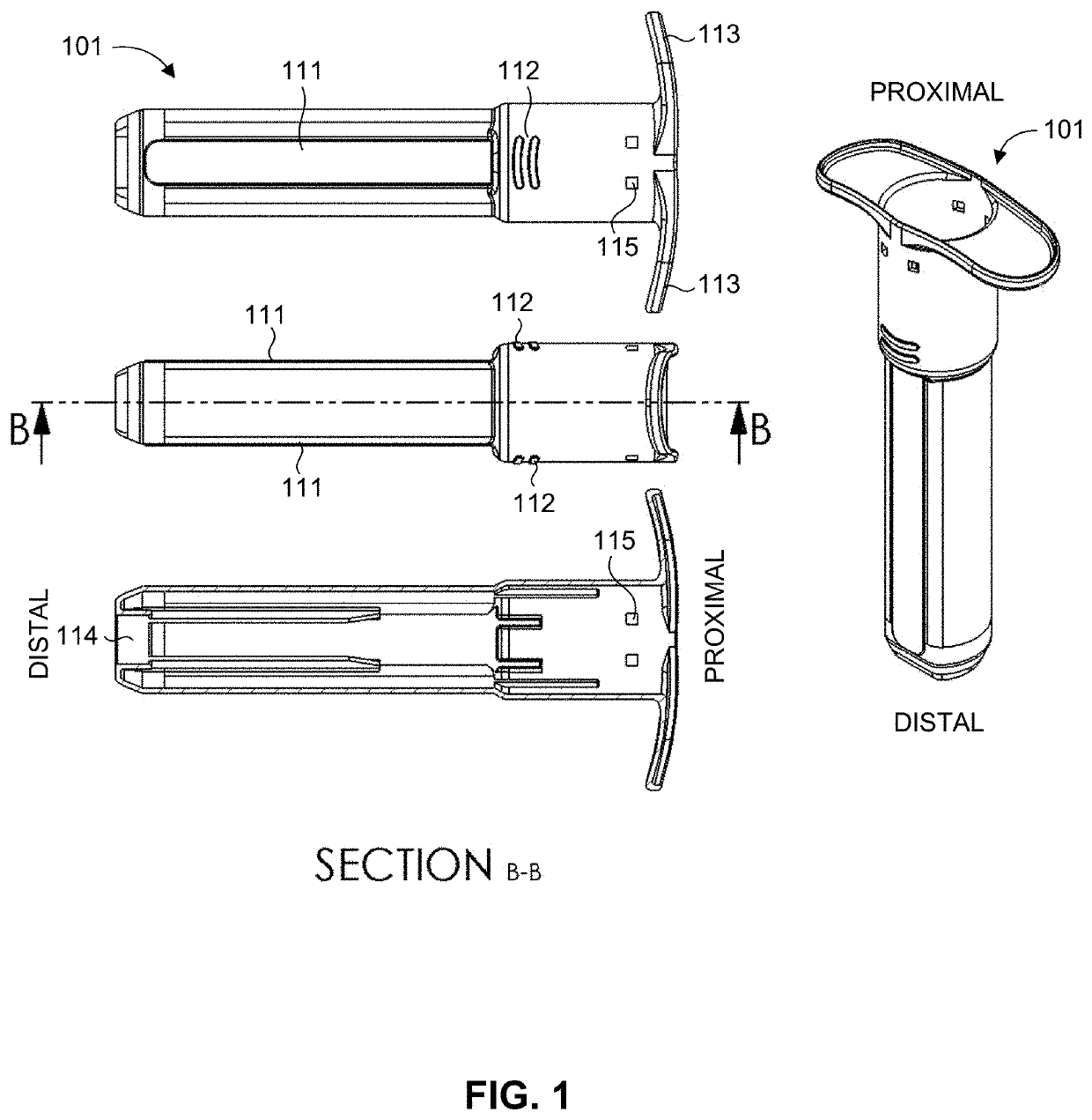
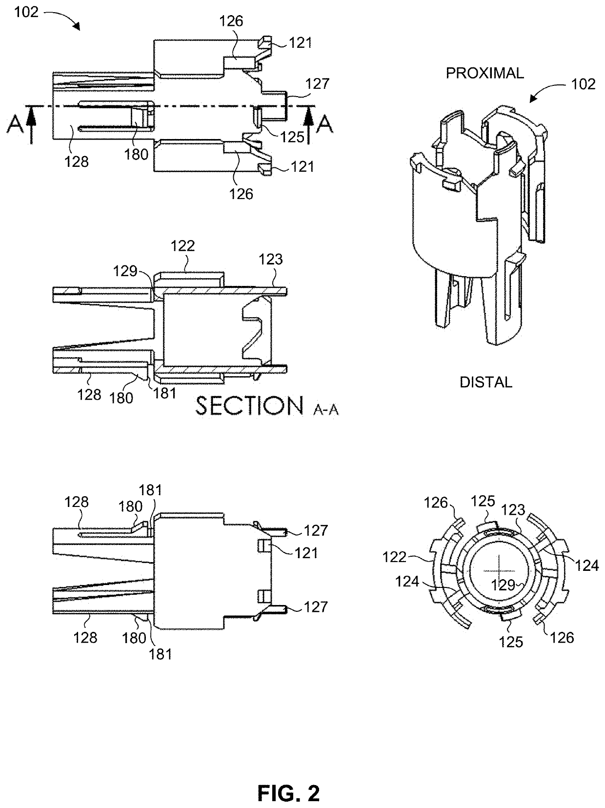
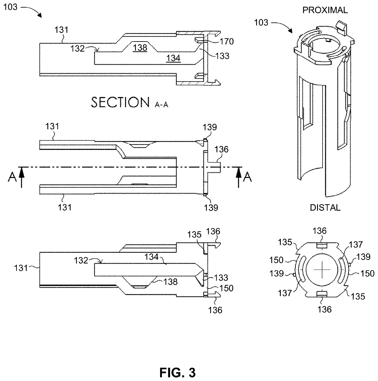
[0052]Reference is now made to FIGS. 1 through 14, which collectively illustrate a safety needle assembly, generally referenced 100, according to the present invention. Assembly 100 includes an external housing (EH) 101, an internal housing (IH) 102, a rotating sleeve (ROS) 103, a biasing element (BE) 104, an activation fork (AF) 105, and a syringe 106. Assembly 100 has a distal end and a proximal end, which is depicted in FIG. 1 in the context of external housing 101, where the distal end faces away from the user holding assembly 100 and towards the injection site. Assembly 100 is also defined by a longitudinal axis, extending lengthwise along the assembly between the proximal and distal ends, where an “axial” direction corresponds to a direction parallel to the longitudinal axis (i.e., towards or away from the proximal or distal ends), whereas a “radial” direction corresponds to a direction orthogonal to the longitudinal axis, and extending radially therefrom.

[0053]FIG. 1 is an il...

second embodiment

[0071]Reference is now made to FIGS. 15 through 27, which collectively illustrate a safety needle assembly, generally referenced 200, according to the present invention. Assembly 200 includes an external housing (EH) 201, an internal housing (IH) 202, a locking sleeve (LOS) 203, a biasing element (BE) 204, an activation fork (AF) 205, and a syringe 206. Assembly 200 has a distal end and a proximal end, which is depicted in FIG. 15 in the context of external housing 201, where the distal end faces away from the user holding assembly 200 and towards the injection site. Assembly 200 is also defined by a longitudinal axis, extending lengthwise along the assembly between the proximal and distal ends, where an “axial” direction corresponds to a direction parallel to the longitudinal axis (i.e., towards or away from the proximal or distal ends), whereas a “radial” direction corresponds to a direction orthogonal to the longitudinal axis, and extending radially therefrom.

[0072]External housi...

third embodiment

[0089]Reference is now made to FIGS. 31 through 47, which collectively illustrate a safety needle assembly, generally referenced 400, according to the present invention. Assembly 400 includes an external housing (EH) 401, an internal housing (IH) 402, a locking sleeve (LOS) 403, a biasing element (BE) 404, an activation fork (AF) 405, a syringe 406, and an outer cap 407. Assembly 400 has a distal end and a proximal end, which is depicted in FIG. 31 in the context of external housing 401, where the distal end faces away from the user holding assembly 400 and towards the injection site. Assembly 400 is also defined by a longitudinal axis, extending lengthwise along the assembly between the proximal and distal ends, where an “axial” direction corresponds to a direction parallel to the longitudinal axis (i.e., towards or away from the proximal or distal ends), whereas a “radial” direction corresponds to a direction orthogonal to the longitudinal axis, and extending radially therefrom.

[0...


PUM


Abstract

An automatically retracting safety needle assembly configured to receive a syringe. The assembly has distal and proximal ends, and comprises:
    • a housing, with internal housing (IH), and a base wall.
    • A moving sleeve (MOS): at least partially within the IH; having a flange wall; axially movable.
    • A biasing element (BE), within the IH, biasing the MOS proximally.
    • A syringe, receiving a plunger rod; movable axially within the IH, and coupled to the MOS.
    • An activation fork (AF), partially disposed within the IH. AF has a guiding arm coupled with the IH and the MOS; preventing motion of the MOS during non-deployment state.
    • An automatic retraction mechanism, retracting the syringe after injection.
    • Deployment: advance plunger rod and the AF axially (distally), until AF guiding arm allows proximal movement of the MOS, retracting the syringe. Distal advancement of plunger rod is constant without an abrupt increase in resistive force; allowing safe disposal.

Description

FIELD OF THE INVENTION[0001]The present invention generally relates to hypodermic needles and syringes, and particularly to safety needle assemblies for safe disposal of hypodermic needles after use.BACKGROUND OF THE INVENTION[0002]A hypodermic needle fitted to a syringe is used for administering injections, such as to inject a medication or drug into a body. The injection is implemented by piercing skin tissue with the needle at a selected body region and then manually depressing a plunger attached to the needle, which forces out the injectant substance through the needle aperture. The needle may be reusable or disposable. For disposable or single use needles, the syringe (and / or the overall assembly encompassing the syringe and the needle) may include safety features to prevent needle reuse, in order to preclude contamination and to prevent potential injury from the exposed needle. Needle reuse can result in the transmission of infectious diseases, especially blood-borne viruses (...

Claims


Application Information

Patent Timeline
Patent Type & Authority Applications(United States)
IPC IPC(8): A61M5/32
CPCA61M5/326A61M5/3234A61M2005/3261A61M2005/3267A61M5/28A61M2005/3247
Inventor DAILY, DAVIDRADAY, LIORLEWKONYA, GADCARMEL, EHOUDLAYBOVITCH, ELYASAFSARKOROV, DMITRIBENAROUS, NIRKEENAN, GUY
Owner DALI MEDICAL DEVICES
Why Eureka
Try Eureka