Transluminal delivery system

a technology of transluminal and delivery system, which is applied in the direction of blood vessels, prostheses, manufacturing tools, etc., can solve the problems of incompatibility of design objectives and engineering demands on the delivery system, and achieve the effect of good column strength and high column strength

Active Publication Date: 2012-06-07
CR BARD INC
View PDF5 Cites 17 Cited by
  • Summary
  • Abstract
  • Description
  • Claims
  • Application Information

AI Technical Summary

Benefits of technology

[0008]A striking technical effect of such a “lock up” concept is that, the more shear stress is imposed on the anti-sliding element by the stent, the more the element locks up, to resist that stress. In other words, the stresses imposed by the anti-sliding element on the stent are only as high as they need to be, to stop the stent sliding relative to the inner catheter.
[0009]A similar effect can be engineered, by endowing the abluminal surface of the inner catheter with a plurality of cantilevered filaments with good column strength that extend radially outwardly from the inner catheter shaft to give it a velvet or flock appearance. When one advances the flocked inner catheter into the stent lumen, from one end of the stent lumen, then the end of the stent first encountered by the filaments will push the filaments back so that they trail each from a leading end fixed to the inner catheter that is advancing into the lumen of the stent. Later, when the sheath is retracted to release the stent, and the stent tends to be entrained and carried proximally with the sheath, the free ends of the filaments will press against the luminal surface of the stent and the anchorage of the respective opposite ends of each filament, on the inner catheter, proximally of the free ends of the filaments pressing against the stent, will restrain any further proximal movement of the stent relative to the inner catheter. One can imagine each of the filaments functioning as a miniature pawl, with a tendency to resist sliding of the stent relative to the inner catheter that benefits from a high column strength in each filament.

Problems solved by technology

With stent delivery systems being required to deliver ever more sophisticated stents to ever more challenging locations within the body of a patient, the engineering demands on the delivery systems have never been higher.
To an extent, these design objectives are incompatible.

Method used


Image

  • Transluminal delivery system
  • Transluminal delivery system
  • Transluminal delivery system

Examples


Embodiment Construction

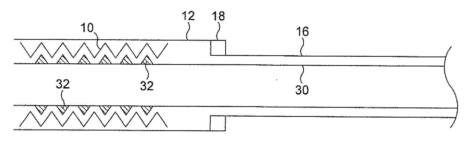
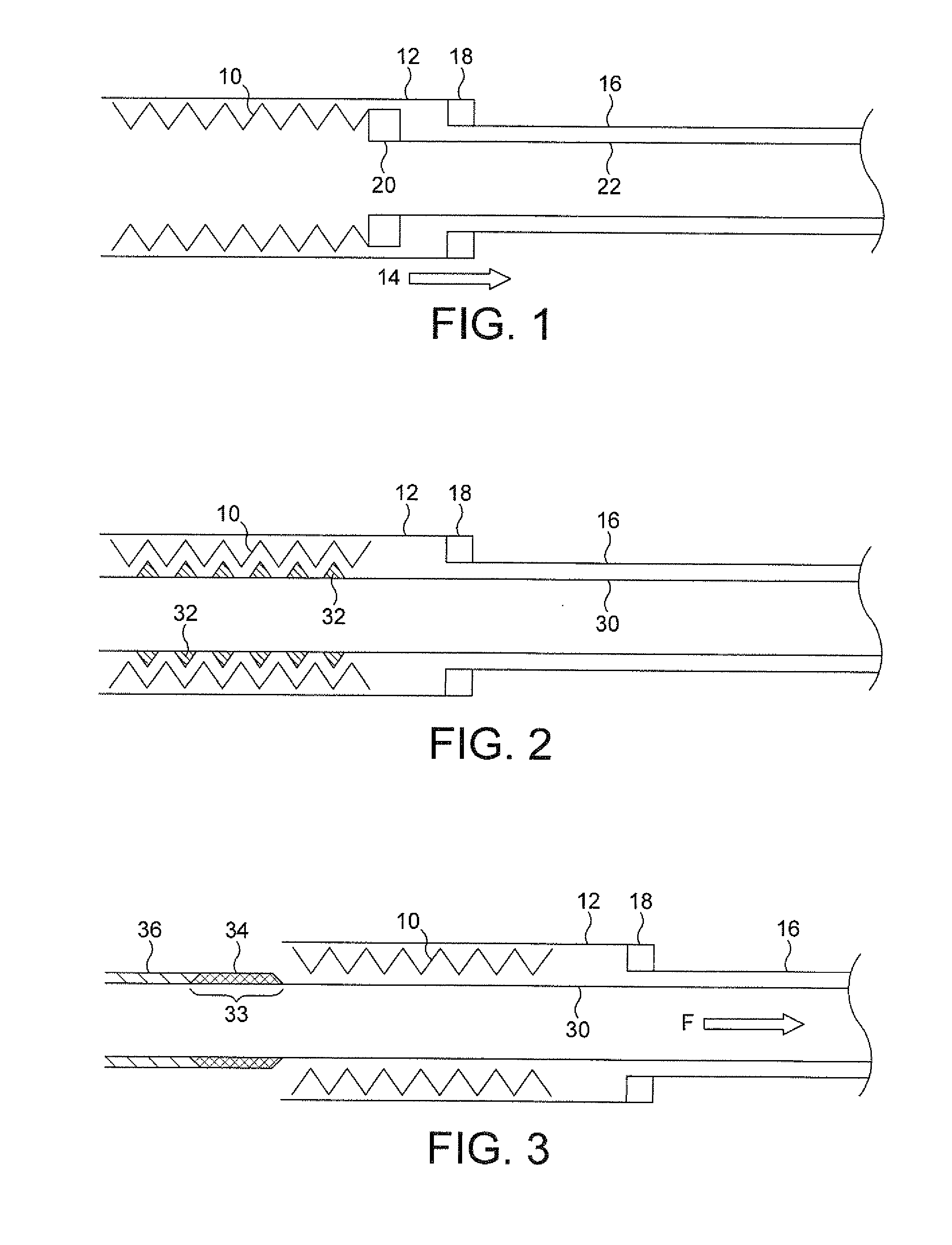
[0017]The schematic drawing of FIG. 1 shows a stent 10 that has been radially crimped to a small diameter for advancement along a lumen to a stenting site within the body of a patient. To release the stent into the bodily lumen a sheath 12 that surrounds the stent and confines it radially is pulled back proximally in the direction of arrow 14 using a pulling device 16 such as a pull tube or pull wire that runs all the way back to the hand unit (not shown) at the proximal end of the transluminal catheter delivery system. Typically, there is some sort of bond, such as with a collar 18, that connects the pulling element 16 with the sheath 12 that surrounds the stent.

[0018]Absent any other structure, then any proximal movement of the sheath 12 will carry the stent with it because the stent is a self-expanding stent and so is continuously pressing on the luminal surface of the sheath 12. To stop the stent 10 moving proximally with the sheath 12, it has been conventional to employ an annu...


PUM

PropertyMeasurementUnit
lengthsaaaaaaaaaa
lengthaaaaaaaaaa
lengthaaaaaaaaaa

Abstract

There is disclosed herein a transluminal delivery system for a self-expanding luminal prosthesis, the system comprising an inner catheter component (30) and a retractable sheath (12) to surround the component thereby to define an annular space to receive the prosthesis (10), the component exhibiting an anti-sliding component, for abutting a luminal surface portion of the prosthesis (10) to restrain the prosthesis from sliding with the sheath (12), and relative to the inner catheter (30), while the sheath retracts relative to the prosthesis to release the prosthesis progressively into the target bodily lumen characterised in that the anti-sliding component is or includes at least one sleeve (36, 50, 66, 76) having a length direction parallel to the longitudinal axis of the annular space and having at least one bound portion (33, 52, 64, 65, 74) of its length that is not free to slide on the inner catheter, and at least one unbound portion of its length with a capability to slide axially on the inner catheter (30) and thereby to exhibit a radial swelling capability, to deliver an increase in the radial thickness of the sleeve (36, 50, 66, 76) while the sheath retracts. Associated methods are also disclosed.

Description

FIELD OF THE INVENTION[0001]This invention relates to a transluminal delivery system for a self-expanding luminal prosthesis, the system comprising an inner catheter component and a retractable sheath to surround the component thereby to define an angular space to receive the prosthesis, the component exhibiting an anti-sliding component, for abutting a luminal surface portion of the prosthesis to restrain the prosthesis from sliding with the sheath, and relative to the inner catheter, while the sheath retracts relative to the prosthesis to release the prosthesis progressively into the target bodily lumen.[0002]The invention also relates to a method of connecting a radially inwardly compressed self-expanding stent to an inner catheter within the lumen of the stent so that when the stent is delivered to a stenting site, the stent is retained against axial movement, relative to the inner catheter, while a sheath disposed radially outside the stent and imposing a radially inwardly c...

Claims


Application Information

Patent Timeline
Patent Type & Authority Applications(United States)
IPC IPC(8): A61F2/84B23P11/02A61F2/95A61F2/966
CPCA61F2/95A61F2/966Y10T29/49863A61F2210/0057A61F2220/0025A61F2002/9665
Inventor WUBBELING, MARTINDIETRICH, DANIELELSASSER, ERHARDWALTER, BEATE
Owner CR BARD INC
Why Eureka
Try Eureka