
Endovascular Delivery System Having Textile Component for Implant Restraint and Delivery

a delivery system and endovascular technology, applied in the field of endovascular delivery system, can solve the problems of increasing the chance of vessel trauma during the procedure, delivery device, and not addressing the potential trauma,

Active Publication Date: 2010-10-21
MEDTRONIC VASCULAR INC
View PDF11 Cites 38 Cited by
  • Summary
  • Abstract
  • Description
  • Claims
  • Application Information

AI Technical Summary

Benefits of technology

[0008]The delivery system may further include a tubular middle member disposed within the outer tubular shaft with a distal end positioned proximate a distal end of the stent-graft held within the tubular textile component. An inner shaft is concentrically disposed within the outer tubular shaft and the middle member and extends through the stent-graft to a flexible tip component, wherein the tip component is positioned at a proximal end of the stent-graft held within the tubular textile component. The outer tubular shaft is longitudinally slidable relative to the middle member, the inner shaft, and the tip component during retraction thereof and deployment of the stent-graft. The middle member acts as a proximal stop to prevent proximal movement of the stent-graft with the tubular textile component during retraction of the outer tubular shaft.

Problems solved by technology

The stiffness of such a catheter shaft, when combined with a relatively stiff guidewire, may straighten the patient's anatomy and thus increase the chance of vessel trauma during the procedure.
Delivery devices having the afore-mentioned configuration do not address the potential trauma caused by introduction and tracking of the catheter devices prior to exposure of the flexible catheter segment and require a two-step delivery process.

Method used


Image

  • Endovascular Delivery System Having Textile Component for Implant Restraint and Delivery
  • Endovascular Delivery System Having Textile Component for Implant Restraint and Delivery
  • Endovascular Delivery System Having Textile Component for Implant Restraint and Delivery

Examples


Embodiment Construction

[0015]Specific embodiments according to the present invention are now described with reference to the figures, wherein like reference numbers indicate identical or functionally similar elements. Unless otherwise indicated, in the following description, the terms “distal” and “proximal” are used with respect to a position or direction relative to the treating clinician. “Distal” and “distally” are positions distant from or in a direction away from the clinician, and “proximal” and “proximally” are positions near or in a direction toward the clinician.

[0016]The following detailed description is merely exemplary in nature. Although the description is in the context of treatment of blood vessels such as the coronary, carotid and renal arteries, the embodiments may also be used in any other body passageways where they are deemed useful.

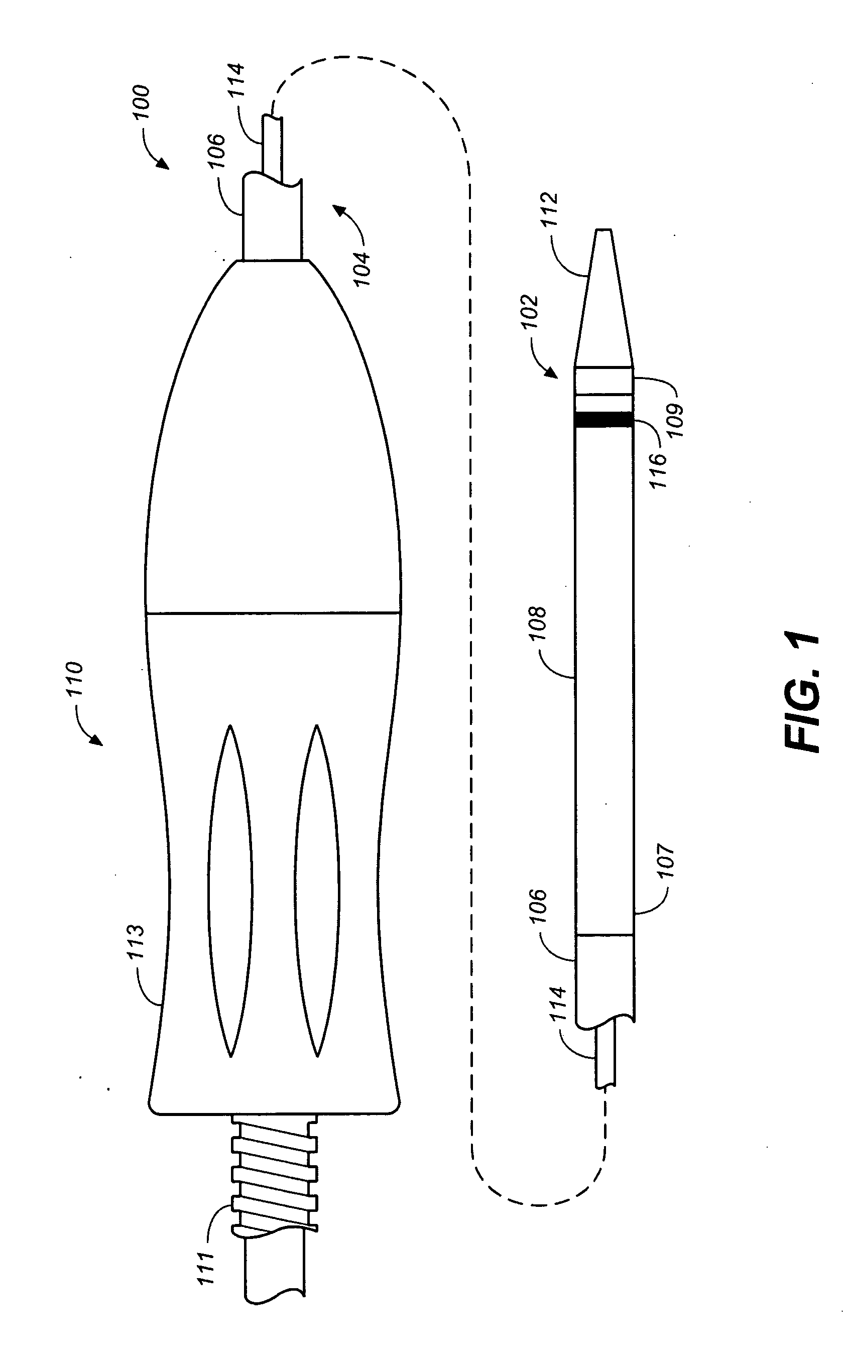
[0017]FIG. 1 is a schematic plan view of a stent-graft delivery system 100 in accordance with an embodiment hereof with a distal portion 102 shown enlarge...


PUM


Abstract

A stent-graft delivery system is disclosed having an outer tubular shaft or sheath with a relatively stiff proximal segment and a distal segment formed from a tubular textile component. The proximal segment being formed from a polymeric tubing and having a distal end attached to a proximal end of the tubular textile component. During tracking of the delivery system through the vasculature, a self-expanding stent-graft is constrained by and within the tubular textile component in a compressed delivery configuration. Upon positioning at a treatment site, such as an aneurysm, retraction of the outer tubular shaft proximally slides the tubular textile component over the stent-graft to expose and deploy the stent-graft. The tubular textile component may be made from strands of one or more biocompatible materials that have been formed into a textile by weaving, braiding, knitting, crocheting, felting or a combination thereof.

Description

FIELD OF THE INVENTION[0001]The invention relates generally to medical devices and procedures, and more particularly to an endovascular delivery system for deploying a stent-graft in a vascular system.BACKGROUND[0002]Prostheses for implantation in blood vessels or other similar organs of the living body are, in general, well known in the medical art. For example, prosthetic vascular grafts constructed of biocompatible materials, such as DACRON material or expanded, porous polytetrafluoroethylene (ePTFE) tubing, have been employed to replace or bypass damaged or occluded natural blood vessels. A tubular graft material supported by framework is known as a stent-graft or an endoluminal / endovascular graft. In general, endovascularly delivered stent-grafts typically have framework that includes at least one graft anchoring component that operates to hold the tubular graft in its intended position within the blood vessel. Most commonly, the graft anchoring component is one or more radiall...

Claims


Application Information

Patent Timeline
Patent Type & Authority Applications(United States)
IPC IPC(8): A61F2/06
CPCA61F2/95A61F2/966A61F2/07
Inventor STIGER, MARK
Owner MEDTRONIC VASCULAR INC
Learn More