Tritanium AL Implants and Instrumentation

a technology of titanium al and implants, applied in the field of titanium al implants and instruments, can solve the problems of excess instrumentation, poor implant performance or potential failure, and unstable implants or implants, and achieve the effect of preventing the proximal movement of the drill guid

Active Publication Date: 2020-08-06
K2M
View PDF0 Cites 18 Cited by
  • Summary
  • Abstract
  • Description
  • Claims
  • Application Information

AI Technical Summary

Benefits of technology

[0021]In another aspect, the present disclosure relates to a method of implanting an interbody implant into a mammalian spine. In one embodiment, the method involves steps including: advancing an end of an insertion tool into an intervertebral implant such that a pair of prongs extending from a distal end of a body of the insertion tool pass through a first opening in the implant and a pin extending from the distal end passes through a second opening in the implant; sliding a drill guide onto the insertion tool and over an actuatable element on the body by displacing the actuatable element from a neutral position; and securing the drill guide to the insertion tool through sliding engagement between a first engagement feature on the drill guide and a second engagement feature on the insertion tool along with advancement of the drill guide distally past the actuatable element so that the actuatable element returns to the neutral position and prevents drill guide from sliding axially in a proximal direction.
[0022]In some embodiments, the method may include actuating a control on the insertion tool to advance an inner shaft within the body until the inner shaft is in between the pair of prongs, the advancement of the inner shaft preventing laterally outward facing protrusions on each prong from retreating into the first opening. In some embodiments, actuating the control may include rotating a lever arm attached to the body to cause the inner shaft to advance relative to an outer shaft of the body. In some embodiments, the method includes actuating a detent mechanism in the body to unlock the lever arm and allow rotation of the lever arm.
[0023]In some embodiments, sliding of the drill guide over the actuatable element may involve sliding the drill guide over a button on the body adjacent to the distal end, the button depressing when the drill guide is over the button and the button rising when the drill guide is slid distally past the button, the button thereby preventing proximal movement of the drill guide to hold the drill guide in place on the insertion tool.

Problems solved by technology

When implants are engaged to certain instruments, a problem may arise in that the implant may be engaged to the instrument upside down.
With time, an improper placement of this kind can lead to poor performance of the implant or potentially even failure.
Another challenge with implant insertion instruments is that the implant may be unstable or may move relative to instrument while secured to the instrument.
This may occur due to a lack of a rotational restraint incorporated into the engagement features on the instrument.
However, such drill guides are typically standalone instruments.
This problem of excess instrumentation is exacerbated by the need to have different sizes of insertion instruments and drill guides available, which demands even more instrumentation.
Existing challenges extend to stability of the spinal implants themselves, even when properly placed in an intervertebral disc space.
In some instances, forces acting on the implant may cause screws to back out of their positions in the implanted implant.
This may lead to poor performance or failure of the implant.
Other problems may include limitations on the possible orientations of the implant when inserted into the intervertebral space.

Method used


Image

  • Tritanium AL Implants and Instrumentation
  • Tritanium AL Implants and Instrumentation
  • Tritanium AL Implants and Instrumentation

Examples


Embodiment Construction

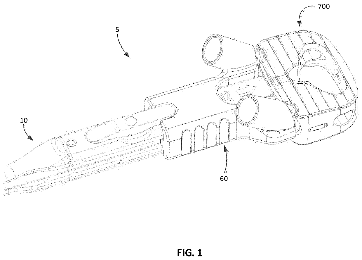
[0053]The present disclosure generally relates to instruments and implants used to repair and reconstruct a mammalian spine. Instruments described include an insertion tool, a drill guide engageable with the insertion tool, and a graft clip, among others. These instruments are used to improve methods of placing an intervertebral implant within an intervertebral space in a reconstructive surgery. Further, various implants used with such instruments are also described herein. One example of an implant insertion system 5 is shown in FIG. 1 and includes an insertion tool 10 and a drill guide 60. In the illustrated system, an intervertebral implant 700 is secured to the insertion tool. These components improve the ability of a user to engage an implant with an instrument and also improve the ability of the user to properly secure the implant in the correct position within a body of a patient. The use of the term “user” herein should be construed broadly to mean the person or machine (e.g...


PUM


Abstract

In some embodiments, the present disclosure relates to a system that includes an insertion tool and a drill guide. The insertion tool includes a body with a distal portion and a distal end. The body has a first engagement feature extending longitudinally along the distal portion and two arms extending longitudinally from the distal end of the body. The drill guide includes two bores and an open faced channel therebetween. The open faced channel includes a second engagement feature slidably engageable with the first engagement feature on the body of the insertion tool. The two bores are adapted for the disposal of a fastener driver tool therethrough.

Description

CROSS-REFERENCE TO RELATED APPLICATION[0001]This application claims the benefit of the filing date of U.S. Provisional Patent Application No. 62 / 799,360, filed Jan. 31, 2019, the disclosure of which is hereby incorporated by reference herein in its entirety.BACKGROUND OF THE INVENTION[0002]A variety of instruments are often used to advance and place implants into an intervertebral space in the spine as part of a spinal reconstructive surgery. When implants are engaged to certain instruments, a problem may arise in that the implant may be engaged to the instrument upside down. Such a result may occur because the engagement features on each of the instrument and the implant are symmetrical about an axis across a width of the implant, so the implant may be engaged whether it is oriented with a superior side up or an inferior side up. With time, an improper placement of this kind can lead to poor performance of the implant or potentially even failure. Another challenge with implant inse...

Claims


Application Information

Patent Timeline
Patent Type & Authority Applications(United States)
IPC IPC(8): A61F2/46A61F2/44A61B17/17A61F2/30
CPCA61F2/30749A61F2/442A61B17/1757A61F2/4611A61F2002/30517A61F2002/30514A61F2002/30481A61F2/4455A61F2002/4627A61F2002/30782A61F2002/30904A61F2002/30593A61F2002/3092A61F2/447A61F2002/3049A61F2002/30784A61F2310/00023B60R19/023
Inventor SCHULTZ, CHRISTIAN KARLMILZ, BRYAN D.SOSNOV, ZINOVIYHAIGHT, BRIANZIELINSKA, JUSTYNAGRAHAM, SHAWN
Owner K2M
Why Eureka
Try Eureka