Methods and systems for constraint of spinous processes with attachment

a technology of spinous processes and constraints, applied in the field of medical methods and apparatuses, can solve the problems of other embodiments having limited compliance or flexibility, and achieve the effect of little or no restriction or resistance to spine extension

Pending Publication Date: 2022-10-27
THE BOARD OF TRUSTEES OF THE LELAND STANFORD JUNIOR UNIV +1
View PDF0 Cites 0 Cited by
  • Summary
  • Abstract
  • Description
  • Claims
  • Application Information

AI Technical Summary

Benefits of technology

[0017]In all cases, the tether structure will typically provide little or no restriction or resistance to extension of the spine. Most often, the tether structure will be free from components or other structures which are located between the adjacent spinous processes or between the spinous processes and the adjacent sacrum. In other instances, however, a cross-member or other low profile structure m

Problems solved by technology

The strap will usually be non-compliant but could in oth

Method used


Image

  • Methods and systems for constraint of spinous processes with attachment
  • Methods and systems for constraint of spinous processes with attachment
  • Methods and systems for constraint of spinous processes with attachment

Examples


Embodiment Construction

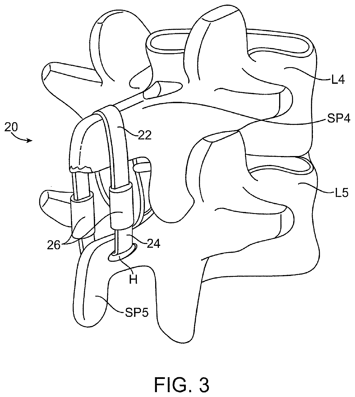
[0029]Referring now to FIG. 3, a spinal implant 20 suitable for use in accordance with the methods of the present invention comprises an upper strap 22, a lower strap 24, and a pair of compliance members 26 joining the upper and lower straps. Typically, the upper and lower straps 22 and 24 will be non-distensible but will be joined to the compliance members 26 so that they can be expanded from a constricted configuration, as shown in broken line, when the patient's spine is in a neutral position between flexion and extension, to an expanded configuration (shown in full line) when the patient's spine is in flexion. The compliance members 26 will provide a force which acts against the extension of the spinous processes SP4 and SP5, as generally described in prior patent application U.S. 2005 / 0216017, which has been previously incorporated herein by reference. In contrast to the teachings of the '017 application, however, the lower strap 24 is non-fixedly attached to the spinous proces...


PUM


Abstract

Spinal implants for limiting flexion of the spine are implanted between a superior spinous process and an inferior spinous process or sacrum. The implants include upper straps which are placed over the upper spinous process, while the lower portions of the implant are attached to the adjacent vertebra or sacrum. The attachments may be fixed, for example using screws or other anchors, or may be non-fixed, for example by placing a loop strap through a hole in the spinous process or sacrum.

Description

CROSS REFERENCE TO RELATED APPLICATIONS[0001]This application is a continuation of U.S. patent application Ser. No. 16 / 140,147, filed on Sep. 24, 2018, now U.S. Patent Application Publication No. 2019 / 0262043, which is a continuation of U.S. patent application Ser. No. 15 / 409,436, filed Jan. 18, 2017, now U.S. Pat. No. 10,080,589, which is a continuation of U.S. patent application Ser. No. 14 / 875,495, filed on Oct. 5, 2015, Publication No. US-2016-0256201-A1, which is a continuation of U.S. patent application Ser. No. 13 / 958,323, filed on Aug. 2, 2013, now U.S. Pat. No. 9,149,304, which is a continuation of U.S. patent application Ser. No. 11 / 827,980, filed on Jul. 13, 2007, now U.S. Pat. No. 8,523,904, which claims the benefit of U.S. Provisional Patent Application No. 60 / 862,085, filed on Oct. 19, 2006, each of which is herein incorporated by reference in its entirety.[0002]U.S. patent application Ser. No. 11 / 827,980 is also a continuation-in-part of U.S. patent application Ser. N...

Claims


Application Information

Patent Timeline
IPC IPC(8): A61B17/70A61B17/84
CPCA61B17/7067A61B17/7055A61B17/842A61B17/7062A61B17/7053A61B17/846A61B17/683A61B2017/7073A61B2017/0417A61B2017/00862
Inventor ALAMIN, TODDBENNETT, IANFIELDING, LOUISCAHILL, COLIN
Owner THE BOARD OF TRUSTEES OF THE LELAND STANFORD JUNIOR UNIV
Why Eureka
Try Eureka