Image forming apparatus

Pending Publication Date: 2022-10-27
CANON KK
View PDF2 Cites 1 Cited by
  • Summary
  • Abstract
  • Description
  • Claims
  • Application Information

AI Technical Summary

Benefits of technology

This patent is about an image forming apparatus that makes pictures on paper. The apparatus includes a rotating member and a driving unit that drives it. The driving unit has two support members that hold the driving force of the driving source and the rear end of the rotating shaft. The first support member has a hole that allows a fastening member to attach it to the second support member. The second support member is located upstream of the first member and has a mounting portion that contacts it. This design ensures that the apparatus is stable and secure during use.

Problems solved by technology

That is, when foreign matter such as dust enters the space where the drive gear is disposed from the outside and adheres to the drive gear, rotational fluctuation occurs in the rotating member driven by the driving unit, and image defects such as periodic band-shaped density unevenness (referred to as banding or the like) may occur in the image formed on the recording material.
In addition, when foreign matter adhering to the drive gear is caught in the drive gear, abnormal noise occurs.
The metal powder adhered to the drive gear causes the above-described image defect and abnormal noise similarly to foreign matter such as dust entering from the outside.
However, when a fastening region is newly secured in the support plate, the driving unit has to be increased in size, and accordingly, it is difficult to adopt the driving unit because this goes against the recent demand for miniaturization as an image forming apparatus.
Therefore, it has been conventionally desired to suppress the occurrence of image defects and abnormal noise due to the adhesion of foreign matter to the drive gear caused by the fastening of the screw in the driving unit without increasing the size of the driving unit, but such a configuration has not been proposed yet.

Method used


Image

  • Image forming apparatus
  • Image forming apparatus
  • Image forming apparatus

Examples


Embodiment Construction

Image Forming Apparatus

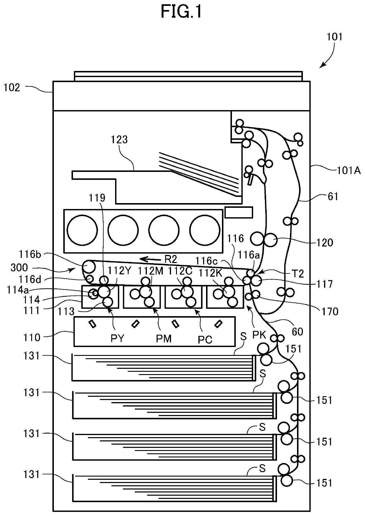
[0020]An image forming apparatus according to the present embodiment will be described with reference to FIG. 1. The image forming apparatus 101 illustrated in FIG. 1 is an intermediate transfer full-color printer. The image forming apparatus 101 includes image forming units PY, PM, PC, and PK that form yellow, magenta, cyan, and black toner images, respectively. The image forming apparatus 101 forms a toner image on the recording material S according to an image signal from a document reading apparatus 102 provided above the image forming apparatus 101 in the vertical direction or an external device (not illustrated) such as a personal computer. Examples of the recording material S include sheet materials such as paper, a plastic film, and cloth. In the present specification, a side on which a user stands when operating an operation panel (not illustrated) in order to operate the image forming apparatus 101 is referred to as a “front surface”, and the opposit...


PUM


Abstract

An image forming apparatus includes a driving unit including a driving source, a drive gear, a first support member that holds the driving source and includes a first support portion that supports one end portion of a rotation shaft of the drive gear, and a second support member that includes a second support portion that supports another end portion of the rotating shaft. The first support member includes a fastening hole disposed in a projection plane obtained by projecting the second support portion in the rotation axis direction of the drive gear. The second support member is disposed upstream of the first support member in a fastening direction, and includes a mounting portion extending so as to be in contact with the first support portion in the projection plane, the mounting portion including an attachment hole, the attachment hole being disposed at a position overlapping the fastening hole.

Description

BACKGROUND OF THE INVENTIONField of the Invention[0001]The present invention relates to an image forming apparatus using electrophotography, such as a printer, a copier, a facsimile, or a multifunction peripheral.Description of the Related Art[0002]In an image forming apparatus such as a printer, a copier, a facsimile, or a multifunction peripheral in which these are integrally combined, for example, a photosensitive drum, a developing sleeve, a driving roller for rotating an intermediate transfer belt, and the like are provided in an apparatus body as a rotating member. Conventionally, in order to drive these rotating members, a driving unit in which motors and drive gears are integrated is attached to a rear plate of an apparatus body. As an example, for example, there has been proposed a driving unit including two support plates that are arranged at both ends of a drive gear in a rotation axis direction and support a rotation shaft of the drive gear, and the drive gear is arrange...

Claims


Application Information

Patent Timeline
IPC IPC(8): G03G15/00
CPCG03G15/757G03G15/00G03G21/186
Inventor KUROSU, YUKITANABE, YUICHI
Owner CANON KK
Why Eureka
Try Eureka