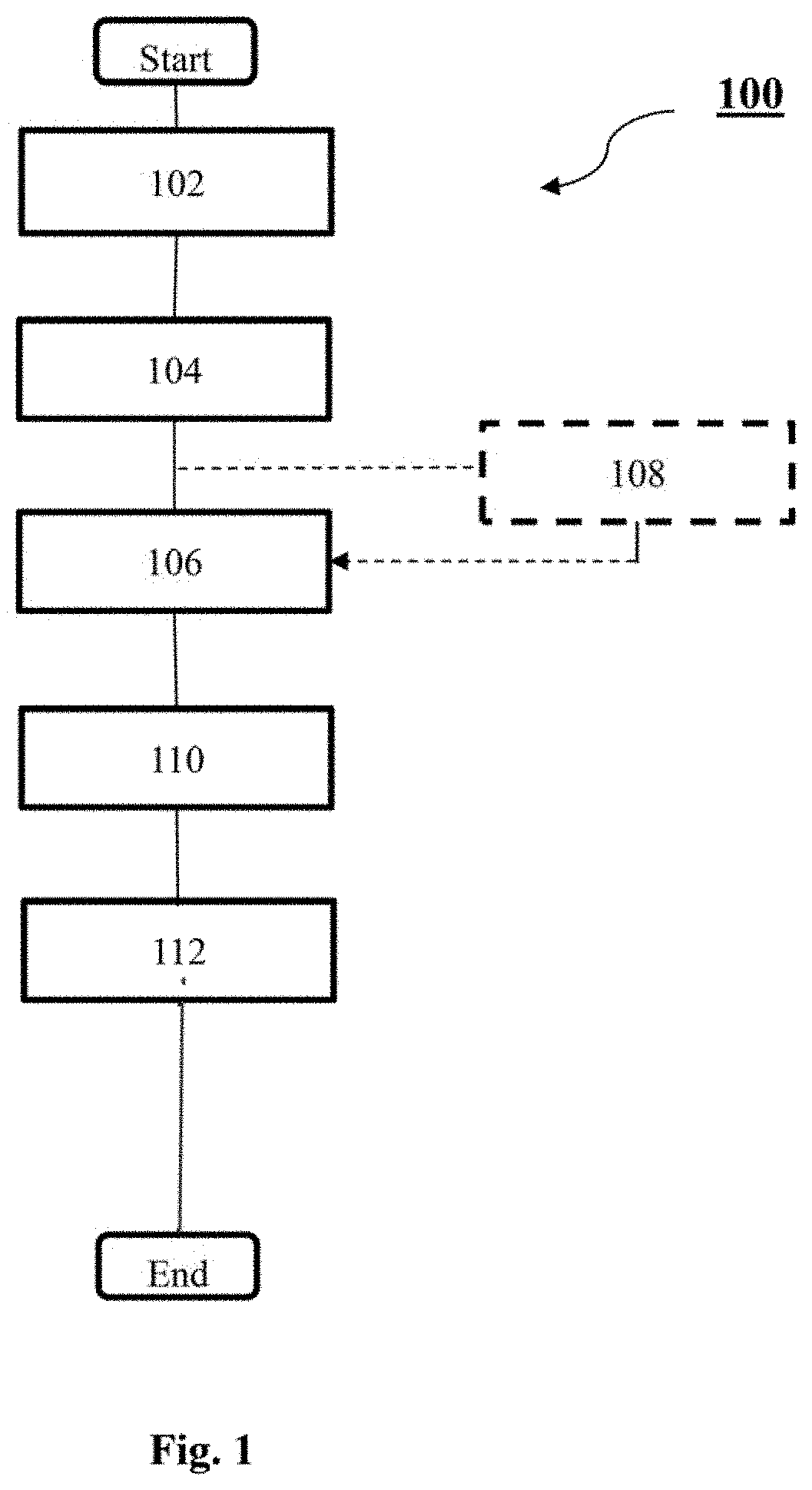
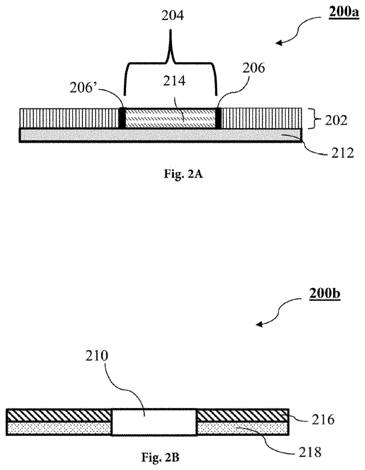
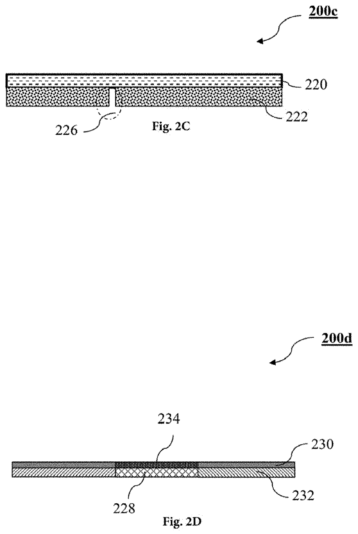
A method of embedding an imaging device within a display
a technology of imaging device and display module, which is applied in the direction of radioation control device, television system, instruments, etc., can solve the problem of compromising the accuracy of driver's monitoring function
- Summary
- Abstract
- Description
- Claims
- Application Information
AI Technical Summary
Problems solved by technology
Method used
Image

Examples
Embodiment Construction
[0034]Hereinafter, an explanation of this disclosure will be discussed in detail, with reference to the drawings.
[0035]The term “configured to” may be interchangeably used with “suitable for”, “having the capacity to”, “designed to”, “adapted to”, “made to”, or “capable of” according to a situation, for example. The term “configured to” may not necessarily mean “specifically designed to” in terms of hardware. Instead, the expression “a device configured to” in some situations may mean that the device and another device or part are “capable of” carrying out a function.
[0036]The term “couple”, “coupled”, “coupling” and its grammatical variation thereof may denote a connection of at least two components, using electrical means, for example electrical connection, optical link, electromagnetic induction, electrostatic charge or any suitable electrical connection means.
[0037]The term “align”, “aligned”, “aligning” and its grammatical variation thereof may denote an arrangement of two or m...
PUM
| Property | Measurement | Unit |
|---|---|---|
| transparent | aaaaa | aaaaa |
| optically transparent | aaaaa | aaaaa |
| transparency | aaaaa | aaaaa |
Abstract
Description
Claims
Application Information
 - R&D Engineer
- R&D Manager
- IP Professional
- Industry Leading Data Capabilities
- Powerful AI technology
- Patent DNA Extraction
Browse by: Latest US Patents, China's latest patents, Technical Efficacy Thesaurus, Application Domain, Technology Topic.
© 2024 PatSnap. All rights reserved.Legal|Privacy policy|Modern Slavery Act Transparency Statement|Sitemap