Eureka AIR delivers breakthrough ideas for toughest innovation challenges, trusted by R&D personnel around the world.

Combination hair styling device

Pending Publication Date: 2022-11-03
CLAYTON MARK +1
View PDF5 Cites 1 Cited by
  • Summary
  • Abstract
  • Description
  • Claims
  • Application Information

AI Technical Summary

Benefits of technology

The present invention is a docking and mooring device that solves the problems of current devices in the market. It includes a base plate with a top and bottom face, each face having a groove. There are also top and bottom sections that can be slidably coupled with the grooves of the base plate using a fastener. The fastener keeps the sections secure without moving relative to each other. The base plate may also have a lip and additional fasteners. The technical effects of this invention are a satisfactory docking and mooring device that can securely attach to a range of objects and prevent them from moving without an external force.

Problems solved by technology

This leaves the user with multiple different devices that take up extra space and are prone to being separated from one another and getting lost.
When multiple hair styling devices are combined into the same device, they are often overly large and rigid devices that are not easily portable and do not allow the user to determine the particular styling ends to carry.
This leaves the user with a device that isn't completely suited to their needs, forcing the user to deal with the inadequacies of the device or forced to carry one or more additional devices that are adequate.
The inventions heretofore known suffer from a number of disadvantages which include: the inability to add, remove, or interchange styling sections, being difficult to swap styling sections, being oversized or awkward to carry, not being versatile, being heavy, having one or more sections prone to breakage or damage, requiring that the user purchase another whole device once the previous device is broken or worn out, and being difficult to hold or use.

Method used


Image

  • Combination hair styling device
  • Combination hair styling device
  • Combination hair styling device

Examples


Embodiment Construction

[0028]For the purposes of promoting an understanding of the principles of the invention, reference will now be made to the exemplary embodiments illustrated in the drawing(s), and specific language will be used to describe the same. It will nevertheless be understood that no limitation of the scope of the invention is thereby intended. Any alterations and further modifications of the inventive features illustrated herein, and any additional applications of the principles of the invention as illustrated herein, which would occur to one skilled in the relevant art and having possession of this disclosure, are to be considered within the scope of the invention.

[0029]Reference throughout this specification to an “embodiment,” an “example” or similar language means that a particular feature, structure, characteristic, or combinations thereof described in connection with the embodiment is included in at least one embodiment of the present invention. Thus, appearances of the phrases an “em...


PUM


Abstract

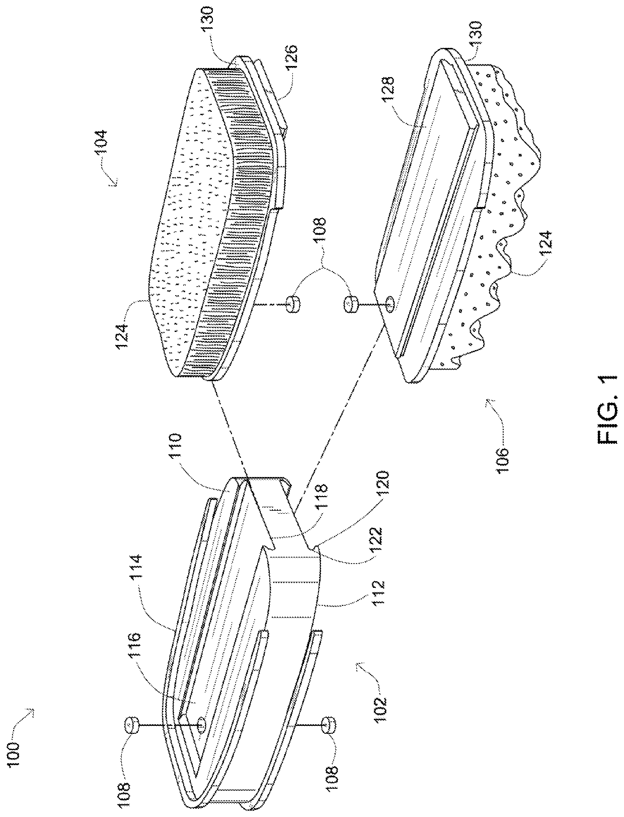
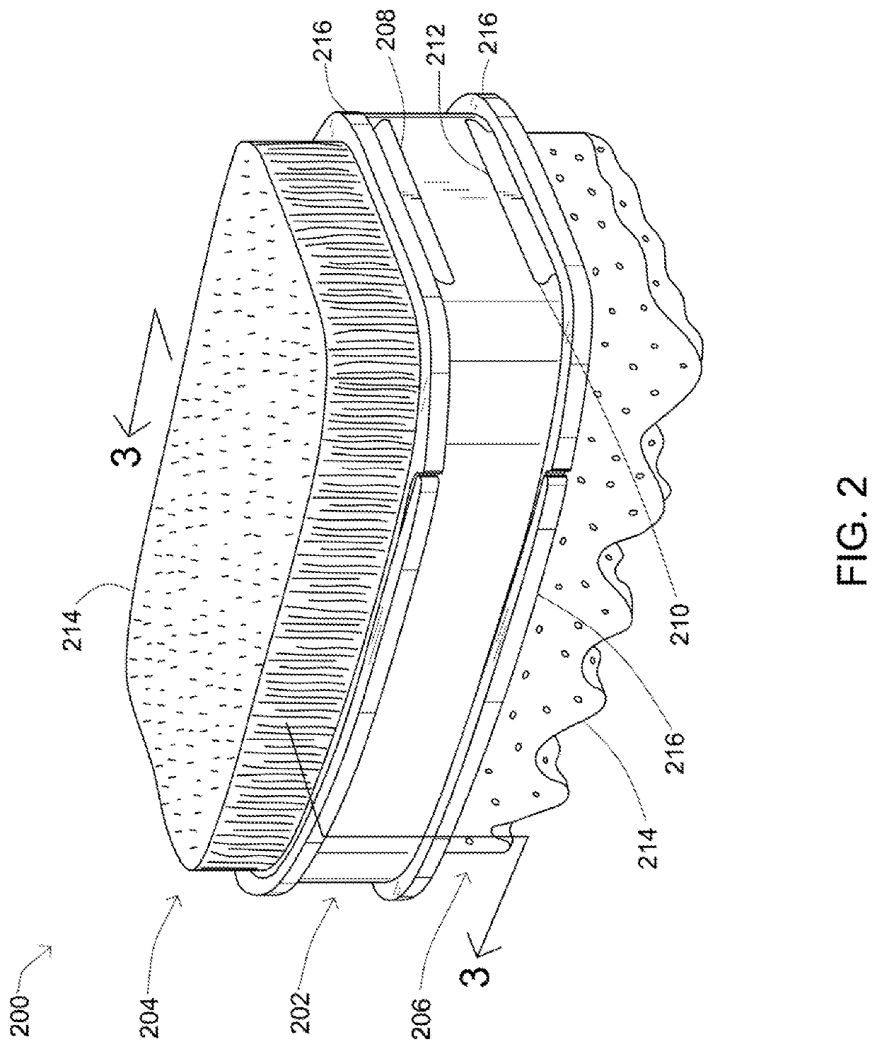
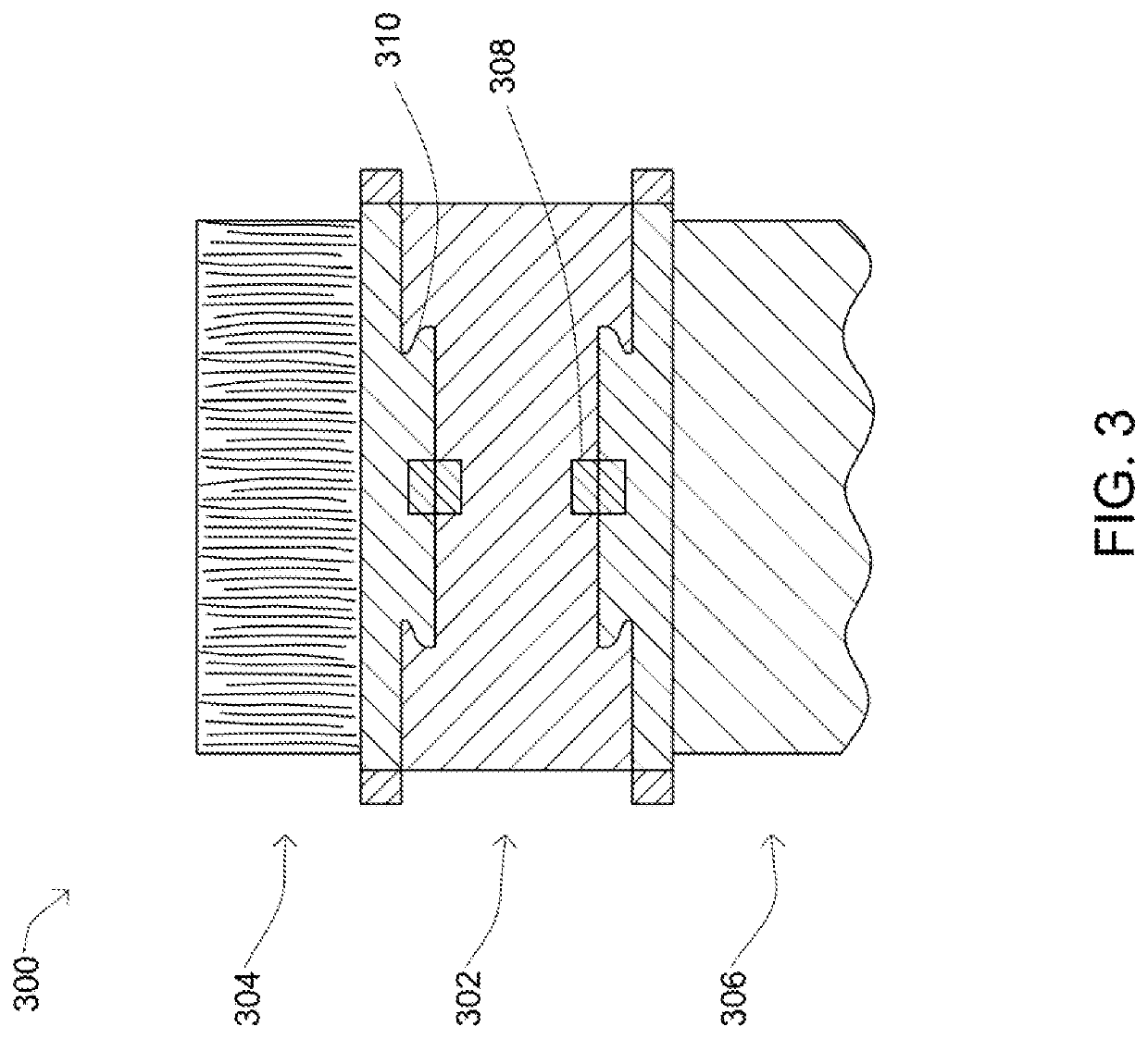
A combination hair styling device, including: a base plate having a top face and a bottom face, both the top face and the bottom face having a groove therein, a top section with a bottom side opposite a first styling side having a first styling structure extending therefrom, the bottom side slidably coupled with the groove of the top face, a bottom section with a top side opposite a second styling side having a second styling structure extending therefrom, the top side slidably coupled with the groove of the bottom face, and a fastener, the fastener able to hold the bottom side within the groove of the top face so that the bottom side and top face do not move relative to one another without an outside force being applied

Description

CROSS-REFERENCE TO RELATED APPLICATIONS[0001]None.FIELD OF THE INVENTION[0002]The present invention relates to combination hair styling devices, specifically to combination hair styling devices that allow for multiple different and interchangeable styling ends.DESCRIPTION OF THE RELATED ART[0003]In the related art, it has been known to use combinations of hair styling devices for creating, undoing, or modifying various hair styles. These hair styling devices are often purchased and used as completely separate devices, of which the user carries multiple to fit their specific needs. This leaves the user with multiple different devices that take up extra space and are prone to being separated from one another and getting lost.[0004]When multiple hair styling devices are combined into the same device, they are often overly large and rigid devices that are not easily portable and do not allow the user to determine the particular styling ends to carry. This leaves the user with a device t...

Claims


Application Information

Patent Timeline
IPC IPC(8): A46B15/00A46B9/00A46B5/00A46B5/02
CPCA46B15/0055A46B9/005A46B5/0095A46B5/02A46B2200/104A46B5/0008
Inventor CLAYTON, MARKBRUMFIELD, REGGIE
Owner CLAYTON MARK
Why Eureka
Eureka Blog
Learn More