Method and Installation for Laser Cutting/Welding

a laser cutting/welding and installation method technology, applied in lasers, laser construction details, laser cooling arrangements, etc., can solve the problems of limiting water cooling, difficult implementation of water cooling devices for some applications, and possible leakage of water pipes, so as to improve the expulsion of particles, increase the cutting/welding performance, and facilitate the supply of vortex tubes

Active Publication Date: 2008-09-11
COMMISSARIAT A LENERGIE ATOMIQUE ET AUX ENERGIES ALTERNATIVES
View PDF12 Cites 14 Cited by
  • Summary
  • Abstract
  • Description
  • Claims
  • Application Information

AI Technical Summary

Benefits of technology

[0015]Moreover, another advantage of the present invention concerns the use of compressed gas as cooling fluid. The supply of the vortex tube is therefore very easy and, above all, the cooling device no longer integrates water, the incompatibility of which with nuclear applications previously constituted a major drawback.
[0016]An additional advantage of the installation according to the invention concerns the presence of a hot gas jet leaving the vortex tube, which can be used judiciously in cooperate with the solder bath in order to further increase the cutting / welding performance.
[0017]Indeed, when the installation is designed for laser cutting, the hot gas leaving via the hot gas outlet from the vortex tube is preferably designed to ensure the expulsion of molten metallic particles outside the solder bath created by the laser beam. As a result, this hot gas ejected from the vortex tube can advantageously be added to a jet of working gas already provided on the cutting installation, which makes it possible to improve the expulsion of particles outside the trench, and therefore to increase cutting performances. It could also, of course, be used as the sole source of working gas without going outside the scope of the invention.
[0018]Moreover, when the installation is designed for laser welding, the hot gas leaving the hot gas outlet of the vortex tube is preferably designed to ensure preheating of the pieces to be welded, and / or protection of the solidified solder bath against ambient air. In the first case, the hot gas is preferably ejected at the front of the laser beam in relation to the direction of welding, in order to play its role of preheating the pieces designed to be welded, and therefore make it possible to obtain increased welding performance. However, in the second case, the hot gas is preferably ejected at the rear of the laser beam in relation to the direction of welding, and even more preferably at the rear of the liquid solder bath. Indeed, this involves protecting the metal coming from the solder bath which has just solidified, and is in the process of cooling, from the ambient air, in order to avoid in particular nitriding and oxidation of the welded metal. An additional interest is that the ejected hot gas makes it possible to act on the thermal welding cycles, unlike with cold gas, which is beneficial for the solidification microstructures, and which can, for example, translate to a decrease in the hardness of the welding seam. Because of this, attaching this hot air jet to the rear of the laser beam and of the solder bath makes it possible to substantially increase the weldability of hard-to-weld materials, such as those known for encountering problems of excessive hardness of the welding seam.
[0019]Preferably, the cooling device comprises a plurality of vortex tubes supplied with compressed gas. In this type of configuration, the vortex tubes can be mounted either in parallel, or in cascade where the hot gas outlet of one vortex tube supplies the inlet of a vortex tube directly consecutive thereto.
[0020]It is noted that in general, the cascade assembly is primarily sought in order to have a hot air flow at high temperature, which makes it well suited to laser welding installations in which it then enables very satisfactory preheating of the pieces to be welded. Moreover, the parallel assembly is essentially adopted in order to have a significant hot gas / cold gas flow, which makes it well suited to laser welding installations in which the large hot air flow then enables very satisfactory expulsion of the metallic particles outside the trench.

Problems solved by technology

However, this type of water cooling device can be difficult to implement for some applications, in particular when the installation is designed to be used under “construction conditions”.
Indeed, water cooling is limiting in that it requires a complex installation integrating pump-type elements and sealed circuits.
Moreover, it is noted that possible leaks can have serious consequences for the construction site.
Furthermore, this water cooling device can even be extremely limiting when the laser cutting / welding installation is designed to be used on a nuclear site, in particular during dismantling of this type of installation, since water then constitutes a fluid creating waste to be processed.
Because of this, it can clearly be seen that uncooled cutting / welding installations can only achieve high cutting / welding performances when they are capable of delivering a strong laser power, as this is likely to cause heating of the laser head, which can lead to its deterioration.
This drawback is therefore particularly limiting for installations requiring the use of high powers for a long period of time, as is generally the case for applications of the “construction site” cutting / welding type, such as dismantling nuclear installations, usually requiring long-lasting interventions with high power often exceeding 4 kW.

Method used


Image

  • Method and Installation for Laser Cutting/Welding
  • Method and Installation for Laser Cutting/Welding
  • Method and Installation for Laser Cutting/Welding

Examples


Embodiment Construction

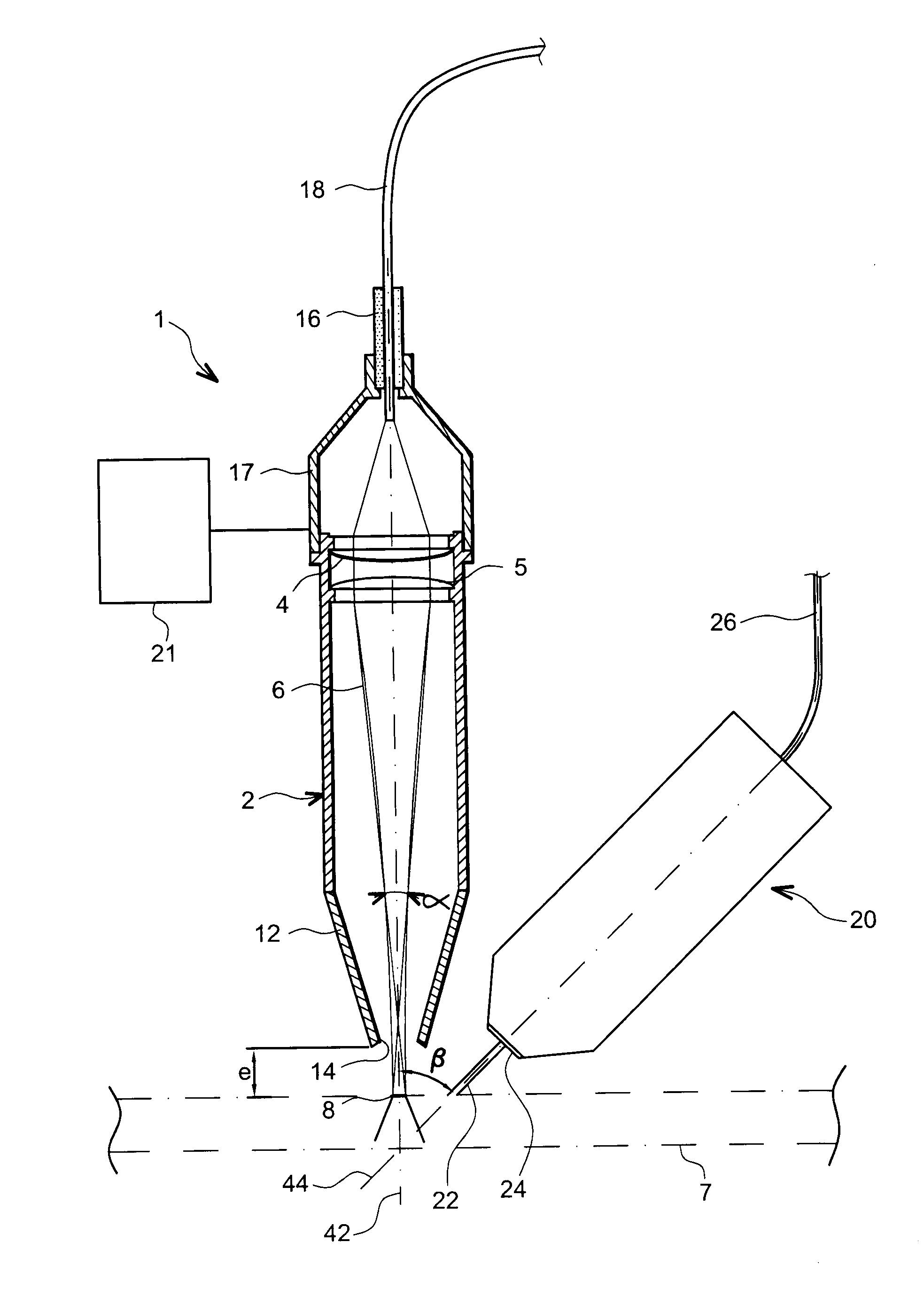
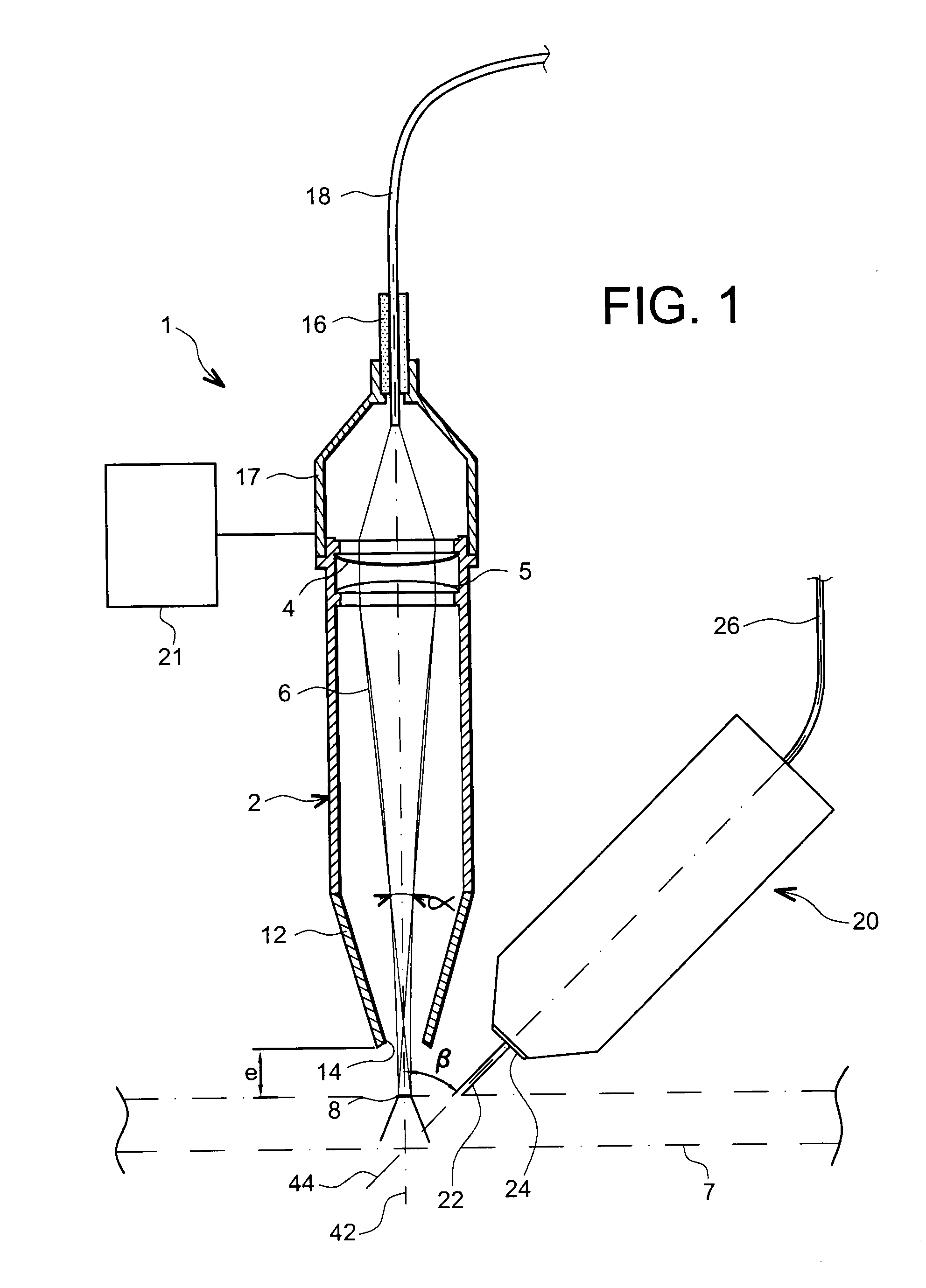
[0041]In reference to the figures, it will be described a laser cutting / welding installation 1 of the Nd-YAG laser type, chosen in particular due to the advantages related to the transport of a laser beam 6 by optical fibers or also due to the advantages with regard to the possibility of having a better interaction between this laser beam 6 and a piece to be cut / welded (referenced 7). Let us note, however, that it would also be quite suitable to use a CO2 laser to implement the invention.

[0042]The invention is designed to be used for pieces of varied thicknesses, and more specifically for pieces having thicknesses greater than approximately 50 mm and which can exceed 100 mm. In any case, the invention proposes a laser cutting / welding device for pieces having significant thicknesses, the limited commonly allowed by those skilled in the art being 10 mm.

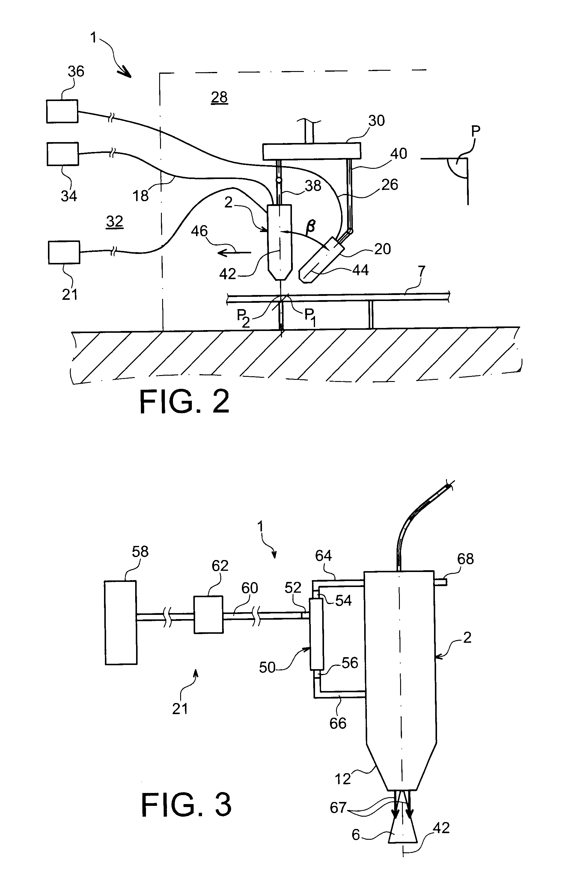
[0043]Likewise, the power delivered to the device 1 is between approximately 4 and 6 kW, this value interval corresponding to the powe...


PUM

PropertyMeasurementUnit
inlet temperatureaaaaaaaaaa
temperaturesaaaaaaaaaa

Abstract

A laser cutting/welding installation including a laser head configured to deliver a laser beam designed to generate a solder bath, the installation also including a cooling device for the laser head. The cooling device includes at least one vortex tube, supplied with compressed gas, the tube including at least one cold gas outlet connected to the laser head for cooling thereof and at least one hot gas outlet.

Description

TECHNICAL FIELD[0001]The technical field of the invention is that of high-power laser cutting and welding methods and installations.[0002]The invention is particularly applicable in the field of laser cutting / welding of materials having significant thicknesses, in particular materials used in installations in the nuclear industry, the naval industry, or the automobile or aeronautic industries.[0003]In this respect, it is noted that an even more privileged application of the invention concerns laser cutting of materials in the framework of dismantling of nuclear installations.PRIOR ART[0004]In this field of cutting / welding pieces by high-power laser, the installations known by the state of the art are typically cooled with the help of a device using water as the cooling liquid.[0005]However, this type of water cooling device can be difficult to implement for some applications, in particular when the installation is designed to be used under “construction conditions”. Indeed, water co...

Claims


Application Information

Patent Timeline
Patent Type & Authority Applications(United States)
IPC IPC(8): H01S3/041B23K26/34
CPCB23K26/1405B23K26/142
Inventor AUBERT, PHILIPPEDE DINECHIN, GUILLAUME
Owner COMMISSARIAT A LENERGIE ATOMIQUE ET AUX ENERGIES ALTERNATIVES
Why Eureka
Try Eureka