Corneal surgical apparatus

a surgical apparatus and corneal technology, applied in the field of corneal surgical equipment, can solve the problems of broken or extended corneal epithelium flap, uneven peeled corneal epithelium, etc., and achieve the effect of satisfying the corneal epithelium flap

Inactive Publication Date: 2007-02-01
NIDEK CO LTD
View PDF10 Cites 0 Cited by
  • Summary
  • Abstract
  • Description
  • Claims
  • Application Information

AI Technical Summary

Benefits of technology

[0004] In view of the problems, therefore, the invention has an object to provide a corneal surgical apparatus which can incise a cornea satisfactorily into a flap shape and which can prepare a satisfactory corneal epithelium flap.

Problems solved by technology

The former is advantageous in that it can peel the corneal epithelium uniformly, but has a problem that the corneal epithelium flap may be broken or extended by the friction with the cornea applanater when the blade is moved backward to the initial position after the flap was prepared.
On the other hand, the latter does not have the same problem, but has another problem that the corneal epithelium may not be uniformly peeled off.

Method used


Image

  • Corneal surgical apparatus
  • Corneal surgical apparatus
  • Corneal surgical apparatus

Examples


first embodiment

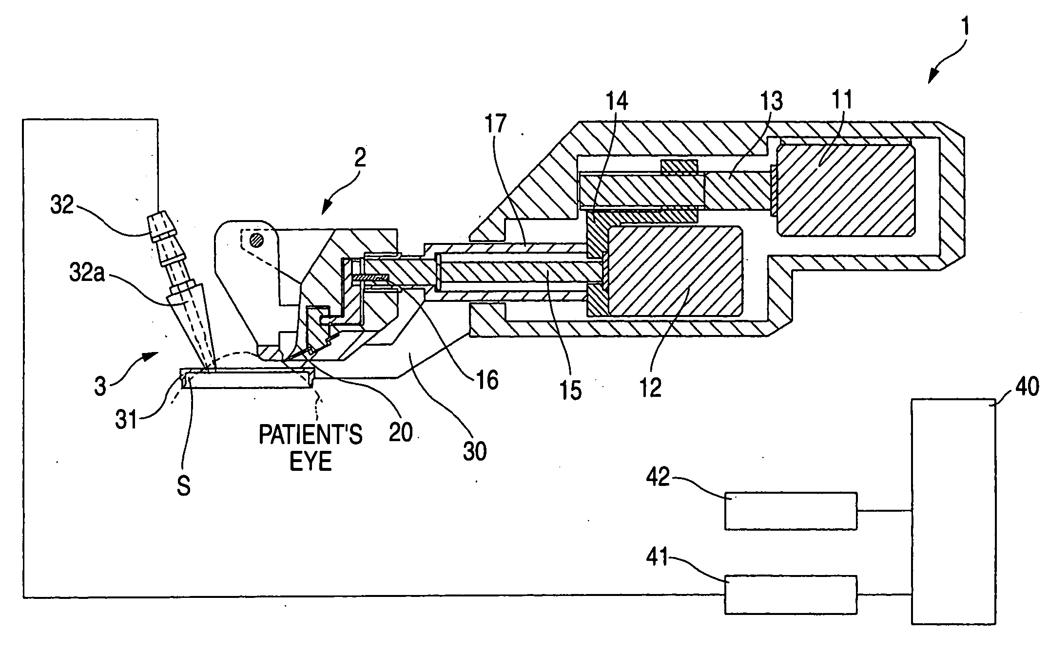
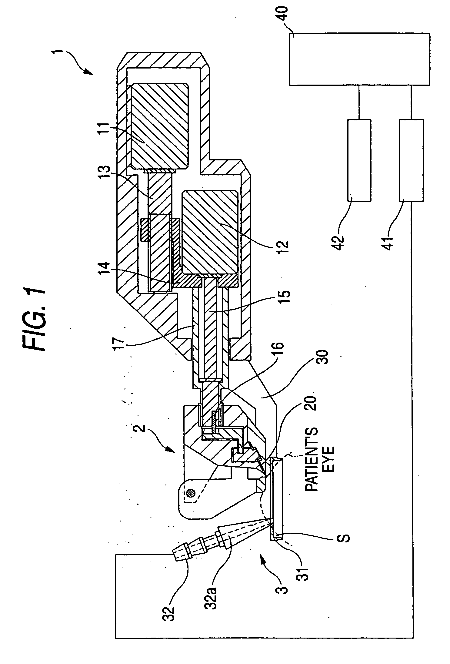
[0033] The corneal surgical apparatus is provided, on the front side (on the lefthand side of FIG. 1) of a body portion (a hand piece portion) 1, with: a cutting head unit 2 which is a blade holder unit that detachably and oscillationally holds a blade 20 for incising and peeling a cornea; and a suction ring unit 3 for fixing the body portion 1 on the patient's eye (an eye to be operated). The suction unit 3 is sucked and fixed to the portion of the patient's eye from the corneal limbus to the conjunctiva.

[0034] The body portion 1 houses a translation motor 11 for rectilinearly moving (translating) the cutting unit 2 over the suction unit 3 in a direction of peeling (incising) the corneal epithelium, and an oscillation motor 12 for oscillating the blade 20 at a high speed in an edge width direction of the blade 20. A connecting member 14 is threaded to a feed screw 13 fixed on a rotating shaft of the motor 11, and the motor 12 and a connecting member 17 are fixed to the connecting ...

second embodiment

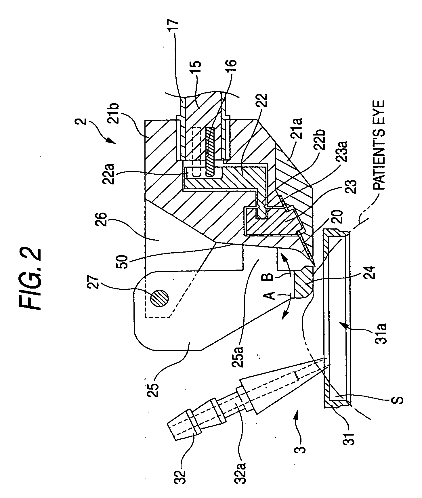
[0048] The invention has been described on the arrangement in which the applanater support 25 for supporting the applanater 24 is turned (rotated) in the peeling direction, i.e., in the forward and backward directions of the cutting unit 2 (the blade 20). However, the invention is not limited thereto. FIG. 5A and FIG. 5B are diagrams showing an apparatus according to a second embodiment. A guide recess 36 for sliding the applanater support 25 back and forth of the cutting unit 2 (the blade 20) is formed in the connecting member 26. The applanater support 25 is provided with a guide protrusion 37 for being engaged with the guide recess 36. As the cutting unit 2 moves forward in the peeling direction, the guide protrusion 37 of the applanater support 25 is positioned in the end of the guide recess 36 on the side of the body portion 1 by the reaction from the cornea and the frictional force between the cornea and the applanater 24, thereby to keep the distance constant between the appl...

third embodiment

[0049]FIG. 6A and FIG. 6B are diagrams showing an apparatus according to a third embodiment. The applanater support 25 is provided at the upper portion thereof with a finger hook 28, on which the finger of an operator to grip the body portion 1 is hooked. When the finger hook 28 is hooked and pulled by the finger of the operator, the applanater support 25 is popped up forward (in the direction A) around the pin 27.

[0050] When the preparation of the corneal epithelium flap is completed (in the state of FIG. 6A), the operator hooks and pulls the finger hook 28 toward the operator. When the finger hook 28 is pulled toward the operator, the applanater support 25 is turned forward around the pin 27 so that it is popped up (to the state of FIG. 6B). With the forward turn (pop-up) of the applanater support 25, the applanater 24 is retracted from the edge of the blade 20. In other words, the distance from the cutting unit 2 (the blade 20) to the applanater 24 becomes longer (the applanater...


PUM


Abstract

A corneal surgical apparatus for incising a cornea in a flap shape, includes: a body portion; and a cutting head unit that is movable back and forth with respect to the body portion and includes a blade holder for holding a blade oscillationally. The cutting head unit includes a cornea applanater mounted through an applanater support for applanating the cornea substantially flatly, the cornea applanater moving forward as the cutting head unit moves forward, and the applanater support includes a movable portion for moving the cornea applanater in a direction apart from the blade holder.

Description

BACKGROUND OF THE INVENTION [0001] The present invention relates to a corneal surgical apparatus for incising a cornea in a flap shape. [0002] As corneal refractive surgery, there has been widely adopted the LASIK (laser assisted in situ keratomileusis) method, in which a flap is formed by incising a portion ranging from a corneal epithelium to a corneal stroma, the corneal stroma is ablated by opening the flap and irradiating it with a laser beam, and the flap is returned (closed) to the initial state. In recent years, however, there has been proposed a new method called the Epi-LASIK (Epithelial LASIK), in which a flap (as will be called a “corneal epithelium flap”) is formed by incising and peeling only a portion of the corneal epithelium and then the corneal stroma is ablated by irradiating it with the laser beam. The corneal surgical apparatus for the Epi-LASIK for preparing the corneal epithelium flap is also proposed. In this apparatus, the corneal epithelium flap is prepared...

Claims


Application Information

Patent Timeline
Patent Type & Authority Applications(United States)
IPC IPC(8): A61F9/00
CPCA61F9/0133
Inventor AMANO, MASANORI
Owner NIDEK CO LTD
Why Eureka
Try Eureka