Simplified primary triggering circuit for the switch in a switched-mode power supply

Active Publication Date: 2013-06-18
MYPAQ HLDG LTD
View PDF104 Cites 3 Cited by
  • Summary
  • Abstract
  • Description
  • Claims
  • Application Information

AI Technical Summary

Benefits of technology

[0011]According to one advantageous embodiment of the present invention, the voltage on an auxiliary winding of the transformer is superimposed on the operating voltage of the trigger circuit by means of a capacitor and optionally one or more resistors. In this way, the zero-crossing of the voltage on the winding can be detected in the trigger circuit. Because this corresponds approximately to the time at which current no longer flows in the transformer, from this, either the time at which the switching transistor is again turned on or the period of the current flow can be determined, so that a constant secondary duty factor can be set. The circuit according to the invention is distinguished primarily by lower costs and reduced external wiring.
[0012]Alternatively, the voltage on the auxiliary winding can be superimposed on the voltage on an additional pin that is used for detecting the primary maximum current (frequently also called “peak current”). Thus, the zero-crossing on this terminal can now be determined. Otherwise, the functioning is the same as in the first embodiment. The advantage of the second embodiment consists primarily of the significantly more precise current regulation, somewhat more precise voltage regulation, and simplified detection of the zero-crossing of the voltage on the winding, bec

Problems solved by technology

The known regulating circuits, however, are usually either relatively expensive in terms of components or demand ti

Method used


Image

  • Simplified primary triggering circuit for the switch in a switched-mode power supply
  • Simplified primary triggering circuit for the switch in a switched-mode power supply
  • Simplified primary triggering circuit for the switch in a switched-mode power supply

Examples


first embodiment

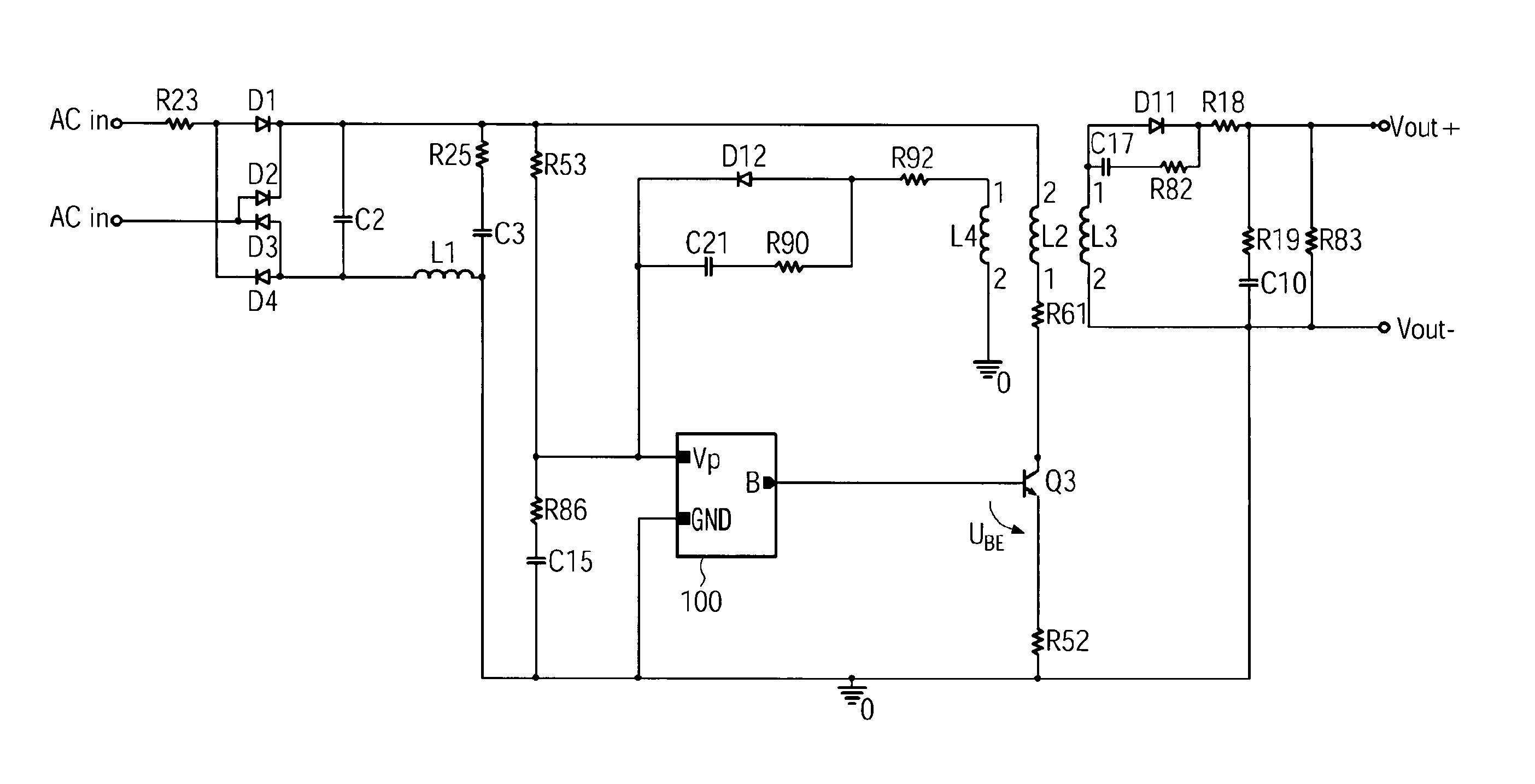
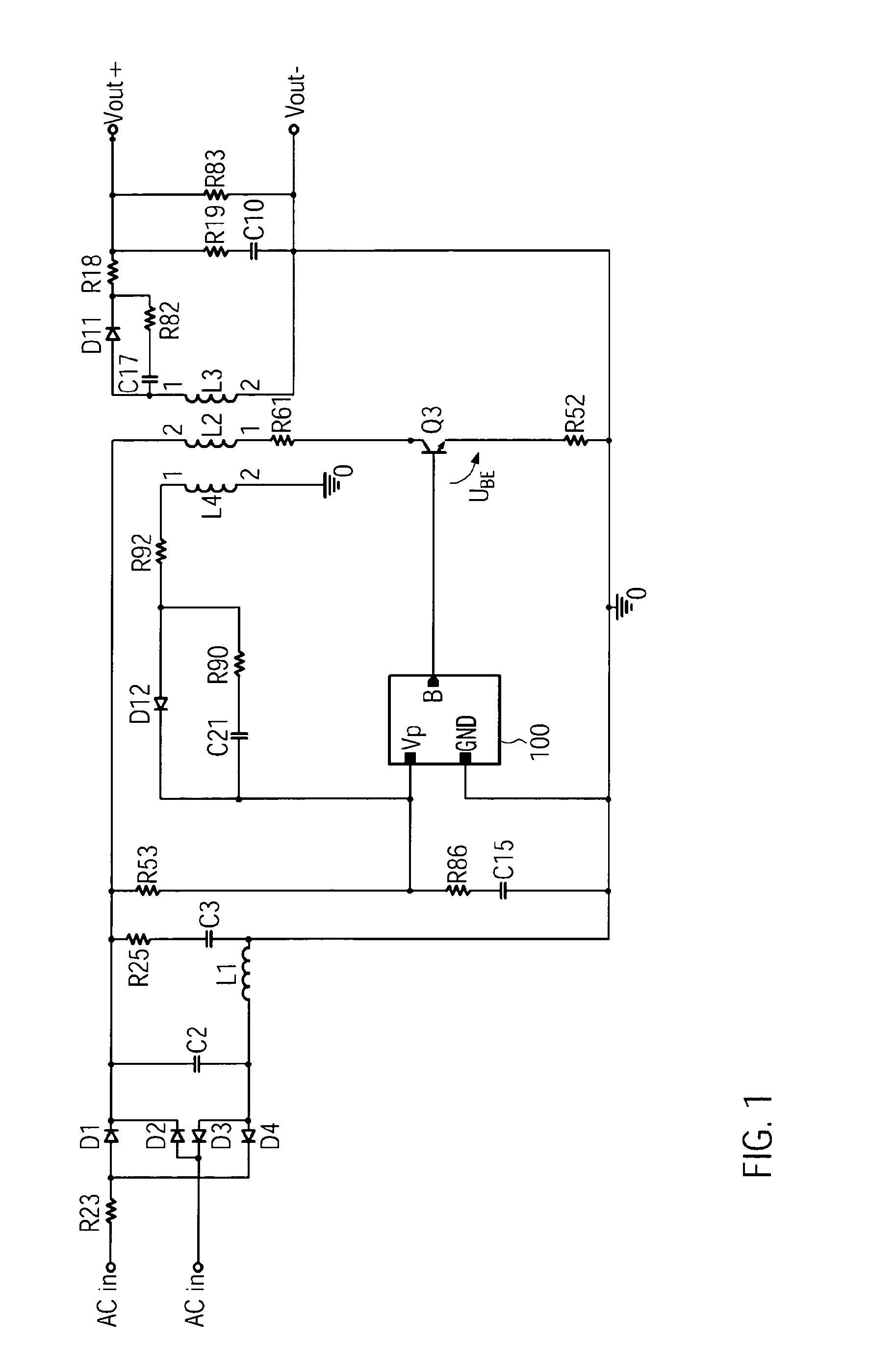
[0037]As a block circuit diagram, FIG. 1 schematically shows a switching power supply according to the present invention in a The alternating voltage ACIN is here first rectified by means of the diode bridge circuit D1 to D4 and guided to the primary-side winding L2 of the transformer after corresponding filtering. The primary-side switch Q3 can interrupt the current flow through the primary-side winding L2 in a defined way in response to a trigger signal on its control terminal. The output voltage Vout is generated on the secondary-side winding L3 of the transformer.

[0038]According to the invention, the trigger circuit 100, which can be fabricated, for example, as an application-specific integrated circuit (ASIC), comprises, in addition to the control terminal that outputs the signal required for triggering the primary-side switch Q3, a ground terminal GND and the operating voltage terminal Vp.

[0039]The operating voltage terminal Vp is connected on one side to the input voltage vi...

second embodiment

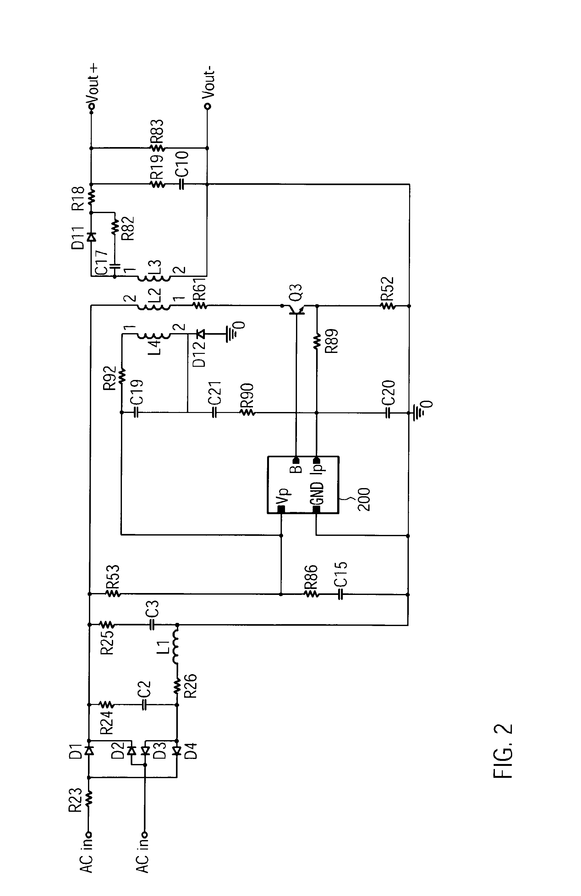
[0049]FIGS. 6 to 8 relate to the trigger circuit 200 that is shown in FIG. 2. In principle, the function of the 4-pin IC is analogous to that of the 3-pin variant.

[0050]In particular, the circuit according to FIG. 6 corresponds in function to that from FIG. 4, wherein an additional input Ip is provided for detecting the current through the transformer. According to the invention, the same input is also used for demagnetization detection. The advantage of the realization in a 4-pin housing is primarily to be seen in improved functionality. In particular, the current regulation is significantly more precise. The voltage regulation is also somewhat more precise, because no additional signal need be superimposed on the regulating voltage and a simplified detection of the zero-crossing of the voltage on the winding can be achieved.

[0051]FIG. 7 shows, in the form of a simplified circuit diagram, another advantageous embodiment of the trigger circuit 200 with a modified startup. In the emb...


PUM


Abstract

The present invention relates to a trigger circuit for a switch in a switching power supply, especially in a primary-side, triggered switching power supply. The trigger circuit here comprises a feedback signal terminal for detecting an auxiliary voltage induced on a primary-side auxiliary winding of a transformer of the switching power supply, a supply voltage terminal for supplying the trigger circuit with a supply voltage, and a ground terminal for connecting the trigger circuit to a ground potential, wherein the feedback signal terminal is formed by the supply voltage terminal and the auxiliary voltage is superimposed on the supply voltage. Alternatively, the voltage of the auxiliary winding could be superimposed on the voltage on an additional pin that is used for detecting the primary peak current.

Description

FIELD OF THE INVENTION[0001]The present invention relates to a trigger circuit for a switch in a switching power supply, especially in a primary-side, triggered switching power supply.BACKGROUND OF THE INVENTION[0002]Switching power supplies are used in numerous electronic devices to generate the low DC voltage required to supply the electronic components with power from a line voltage. Here, in many applications, switching power supplies have become popular compared with conventional line supply circuits with power transformers because they provide better efficiency above a certain power class, and in particular they have smaller space requirements. This is because, instead of using the line voltage, a high-frequency AC voltage is transformed, which can be in the frequency range of 20 kHz to 200 kHz, for example, instead of the 50 Hz or 60 Hz of the line voltage. Because the required number of transformer windings decreases in inverse proportion to the frequency, the I2R losses can...

Claims


Application Information

Patent Timeline
IPC IPC(8): H02M3/335
CPCH02M3/33523H02M2001/0006H02M1/0006
Inventor BERGHEGGER, RALF SCHRODER GENANNT
Owner MYPAQ HLDG LTD
Why Eureka
Try Eureka