
Medical image capturing apparatus

a technology of medical images and capturing apparatuses, applied in image enhancement, tomography, instruments, etc., can solve problems such as inability to capture images in a single place, and achieve the effect of avoiding the formation of thick columns

Pending Publication Date: 2022-11-03
FUJIFILM CORP
View PDF0 Cites 0 Cited by
  • Summary
  • Abstract
  • Description
  • Claims
  • Application Information

AI Technical Summary

Benefits of technology

The present disclosure provides a medical image capturing apparatus that allows a subject to be easily visually recognized from the outside, compared to a case where the number of columns is two, which makes the columns thick. It is preferable that the column to which at least one of the input device or the display is attached has rigidity higher than other columns. This technique allows for improved visibility and easier identification of the subject being examined.

Problems solved by technology

For this reason, considering the installation stability or the like of the imaging unit, the columns are inevitably thick.

Method used


Image

  • Medical image capturing apparatus
  • Medical image capturing apparatus
  • Medical image capturing apparatus

Examples


Embodiment Construction

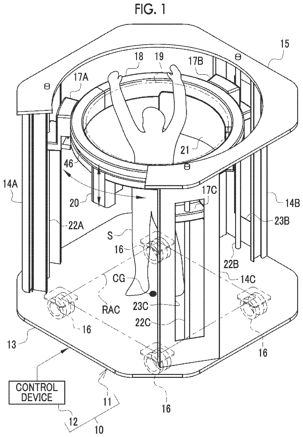
[0053]As shown in FIG. 1 as an example, a CT apparatus 10 is an apparatus that obtains a tomographic image TI (see FIG. 16) of a subject S, and is configured of an apparatus body 11 and a control device 12. The apparatus body 11 is installed, for example, in an imaging room of a medical facility. The control device 12 is installed, for example, in a control room next to the imaging room. The control device 12 is a desktop type personal computer, a notebook type personal computer, or a tablet terminal. The CT apparatus 10 is an example of a “medical image capturing apparatus” according to the technique of the present disclosure.

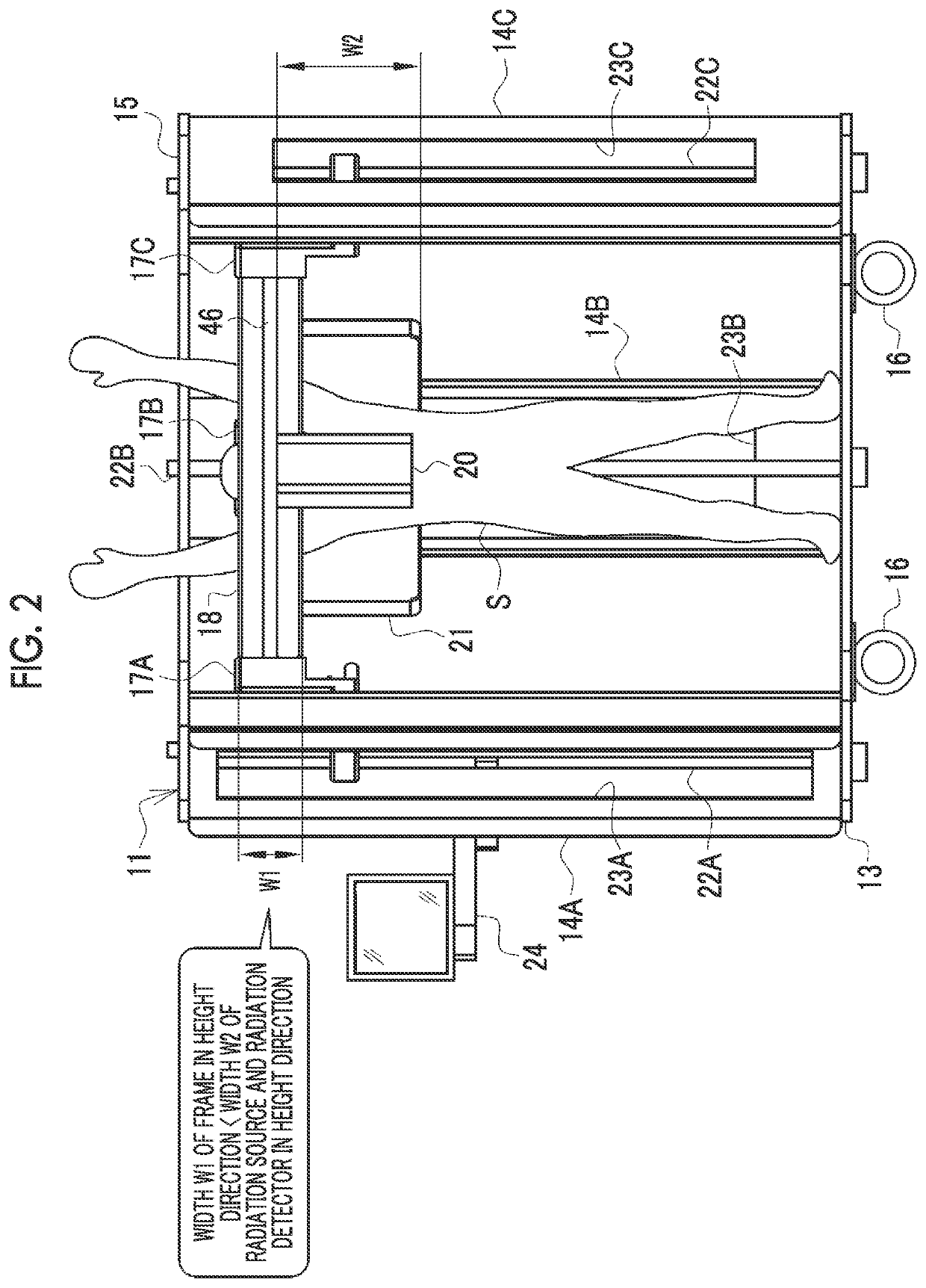
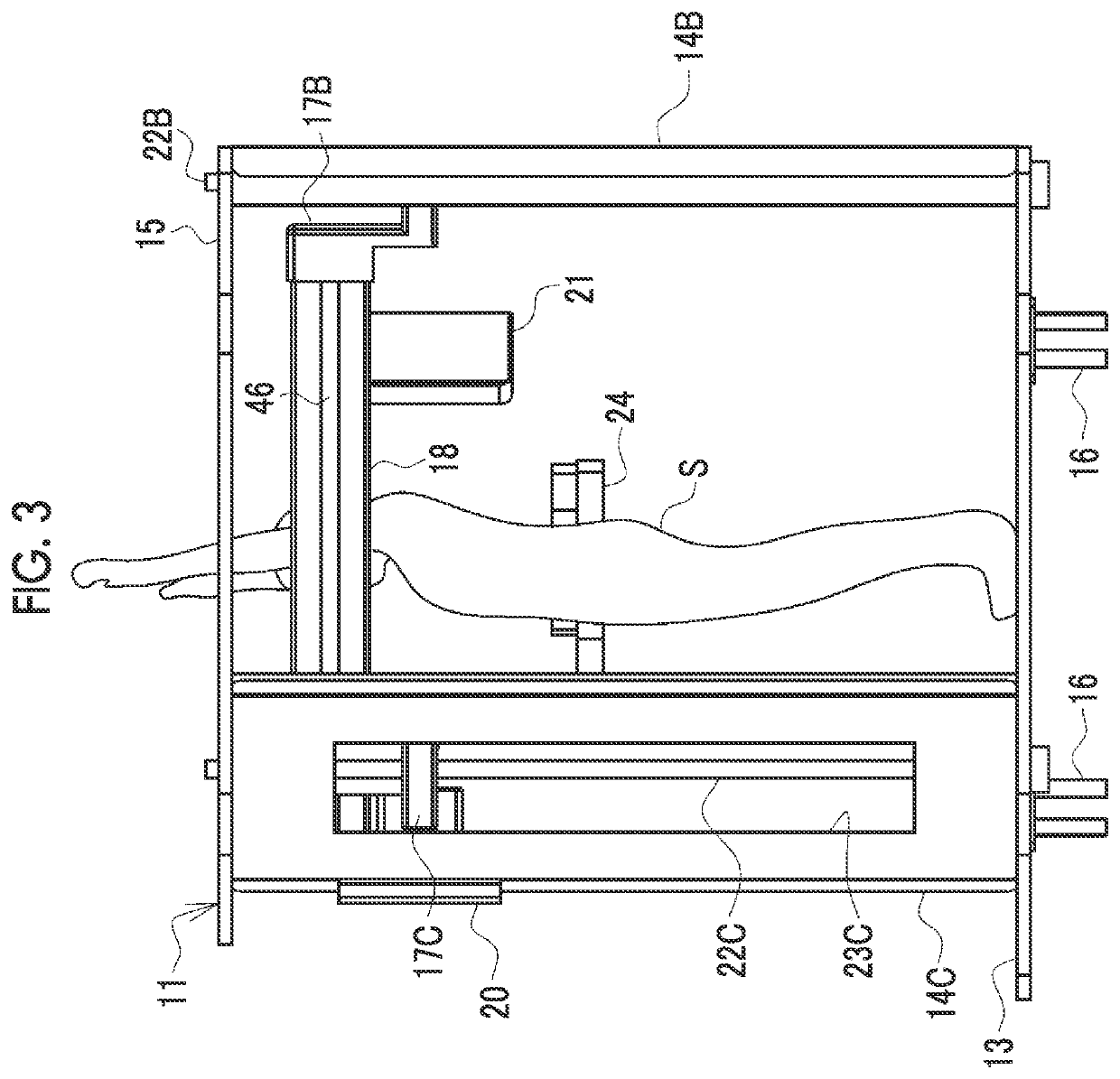
[0054]As shown in FIGS. 1 to 4 as an example, the apparatus body 11 comprises a stage 13, three columns 14A, 14B, and 14C, and a top plate 15. The stage 13 is a flat plate having an octagonal shape. Casters 16 for transport are attached to four corners of a back surface of the stage 13.

[0055]The casters 16 comprise a rotation locking mechanism (not shown), and...


PUM


Abstract

A CT apparatus includes a radiation source that emits radiation, a radiation detector that detects the radiation, an annular frame to which the radiation source and the radiation detector are attached and in which a subject is positioned in a bore, and three columns that hold the frame to be movable up and down in a vertical direction.

Description

CROSS-REFERENCE TO RELATED APPLICATIONS[0001]The present application claims priority under 35 U.S.C. § 119 to Japanese Patent Application No. 2021-076586 filed on Apr. 28, 2021. The above application is hereby expressly incorporated by reference, in its entirety, into the present application.BACKGROUND1. Technical Field[0002]A technique of the present disclosure relates to a medical image capturing apparatus.2. Description of the Related Art[0003]For example, a medical image capturing apparatus, such as a computed tomography (CT) apparatus for imaging a subject in an upright posture described in JP2017-077464A, has been suggested. The CT apparatus described in JP2017-077464A comprises an imaging unit, and two columns that hold the imaging unit. The imaging unit is in an annular shape, and the subject in the upright posture is positioned in a bore. The two columns are disposed in a front-rear direction of the subject. The columns can expand and contract, and accordingly, a height pos...

Claims


Application Information

Patent Timeline
Patent Type & Authority Applications(United States)
IPC IPC(8): A61B6/03G06T7/00
CPCA61B6/035G06T7/0012G06T2207/10081A61B6/0421A61B6/44A61B6/032A61B6/4405A61B6/4275A61B6/4435A61B6/0407A61B6/0478
Inventor TAJIMA, TAKASHIFUKUYO, MASAKAZUSHIMIZUKAWA, SHOKOBAYASHI, TAKEYASUHORIUCHI, HISATSUGUNISHINO, NAOYUKI
Owner FUJIFILM CORP
Learn More