Supercharge Your Innovation With Domain-Expert AI Agents!

Transmission path design apparatus, transmission network topology design method, and transmission path design program

a technology of transmission path and design apparatus, applied in the direction of electrical apparatus, data switching by path configuration, transmission, etc., to achieve the effect of reducing the amount of equipment needed and being easy to design

Pending Publication Date: 2022-11-10
NIPPON TELEGRAPH & TELEPHONE CORP
View PDF36 Cites 0 Cited by
  • Summary
  • Abstract
  • Description
  • Claims
  • Application Information

AI Technical Summary

Benefits of technology

The present invention provides a method, program, and apparatus for designing a transmission path topology that optimizes the use of equipment and reduces the amount of equipment needed to maintain availability against multiple failures. This automates the design process and assists the designer in making informed decisions.

Problems solved by technology

However, to maintaining high availability, quick recovery measures are needed, and therefore, a large-scale maintenance system is needed.
Further, in recent years, enhancement of countermeasures against wide-area disasters has become an important issue.
However, in the case of the redundancy provided by the multi-ring configuration, division of a network and isolation could occur due to a wide-area disaster.

Method used


Image

  • Transmission path design apparatus, transmission network topology design method, and transmission path design program
  • Transmission path design apparatus, transmission network topology design method, and transmission path design program
  • Transmission path design apparatus, transmission network topology design method, and transmission path design program

Examples


Embodiment Construction

[0036]An embodiment of the present invention will be described below with reference to the drawings.

Description of Environment to which Invention is Applied

Configuration Example of Optical Transmission Network

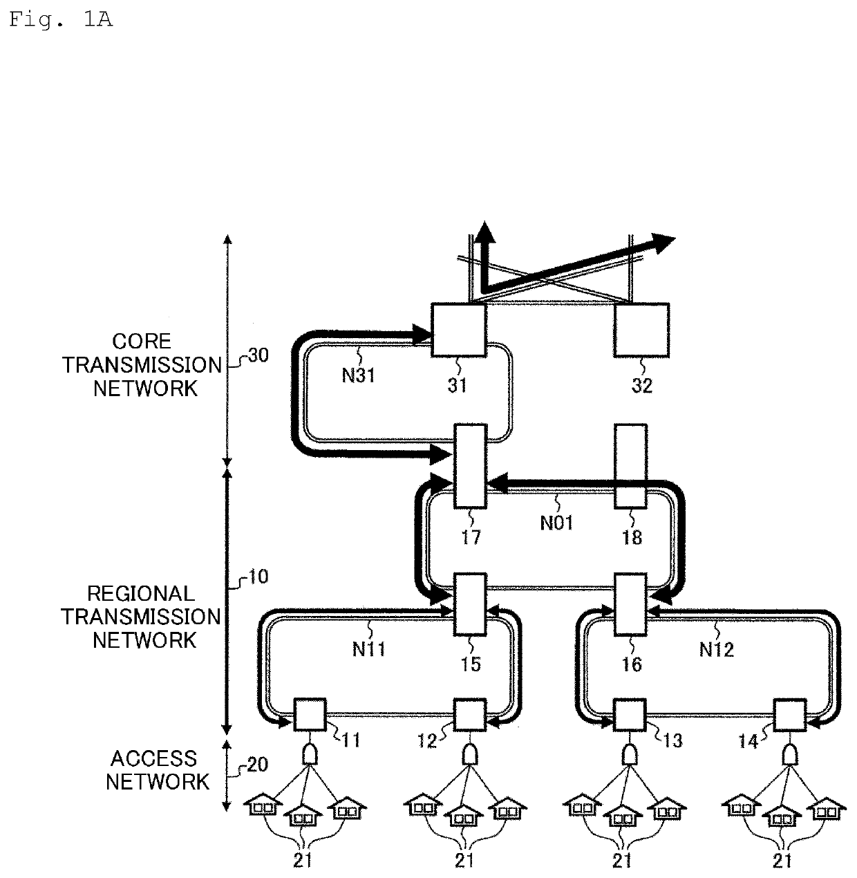
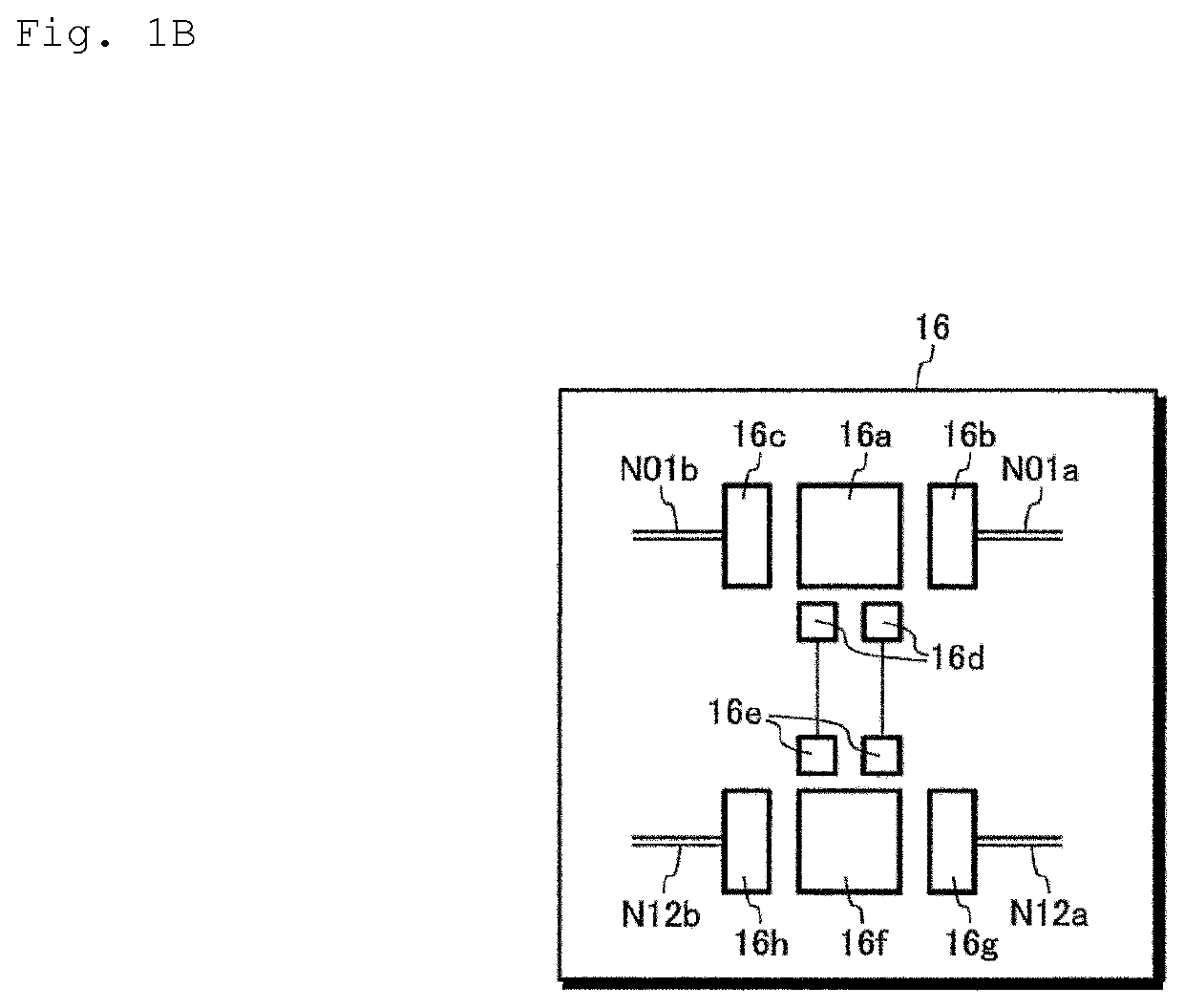
[0037]FIG. 1A illustrates a configuration example of a main part of a wide-area optical transmission network. FIG. 1B illustrates a configuration example of communication equipment in a regional representative building 16 in FIG. 1A. FIG. 1C illustrates a configuration example of communication equipment in a regional building 13.

[0038]The optical transmission network illustrated in FIG. 1A includes a regional transmission network 10, an access network 20, and a core transmission network 30. Optical communication equipment serving as a base station of a communication network is accommodated in an individual building. The access network 20 provides a user with a communication environment by connecting a user terminal 21 in a home or the like to anyone of regional buildings 11, 12...


PUM


Abstract

To easily design a communication path topology optimized in view of reducing the amount of equipment needed under the condition that availability against multiple failures in a network is maintained. A transmission path design apparatus (100) performs: a step (S14) of extracting, from the multiple base stations, a first group of base stations whose number of communication-path routes connected is large, based on transmission network model initial data (D0); a step (S16) of extracting a first group of communication paths connecting the base stations in the first group; a step (S16) of calculating a both-end path value (d_i,j) for each communication path in the first group; and steps (S18 to S24) of determining the communication path whose both-end path value satisfies a predetermined condition as a thinning-out target communication path, and generating output data Dy in which the thinning-out target communication path is reflected on the transmission network model initial data. The optimized output data (Dy) can be generated by extracting a deletable communication path in order from the model of the initial data (D0).

Description

TECHNICAL FIELD[0001]The present invention relates to a transmission path design apparatus, a transmission network topology design method, and a transmission path design program that can be used for designing regional transmission networks or the like.BACKGROUND ART[0002]There is a demand for reducing operating costs of equipment and maintenance of optical transmission networks used for regional transmission networks or the like while maintaining high communication quality and availability as a common infrastructure. In addition, the regional transmission networks, which are desired to efficiently accommodate user traffic, commonly have a multi-ring configuration that simply ensures path redundancy by using a two-direction ROADM (Reconfigurable Optical Add / Drop Multiplexer). However, to maintaining high availability, quick recovery measures are needed, and therefore, a large-scale maintenance system is needed.[0003]Further, in recent years, enhancement of countermeasures against wid...

Claims


Application Information

Patent Timeline
IPC IPC(8): H04L45/24H04L45/12H04L45/02
CPCH04L45/24H04L45/126H04L45/02H04L12/28
Inventor YAMAMOTO, HIROSHIOKA, TOSHIYUKIMAEDA, HIDEKI
Owner NIPPON TELEGRAPH & TELEPHONE CORP
Features
  • R&D
  • Intellectual Property
  • Life Sciences
  • Materials
  • Tech Scout
  • Unparalleled Data Quality
  • Higher Quality Content
  • 60% Fewer Hallucinations
Learn More