
Calibration method and calibration apparatus for knob applicable to touch panel

a technology of calibration apparatus and knob, which is applied in the direction of instruments, computing, electric digital data processing, etc., can solve the problems of affecting the wrong determination of the inability to integrate the knob device and the touch panel to assist the user in controlling, etc., to achieve the accurate position of the center of the knob, improve the stability and reliability of the knob, and prevent the rotation angle of the knob

Pending Publication Date: 2022-11-17
HIMAX TECH LTD
View PDF4 Cites 0 Cited by
  • Summary
  • Abstract
  • Description
  • Claims
  • Application Information

AI Technical Summary

Benefits of technology

The present invention is a calibration method and apparatus that can accurately determine the center of a knob by calculating the positions of sensing pads. This ensures that the rotation angle of the knob is not determined incorrectly, improving the stability and reliability of the knob.

Problems solved by technology

Therefore, how to integrate the knob device and the touch panel to assist user in control has become an issue.
The offset of the position will cause the wrong determination of the rotation angle of the knob, and further affect the stability and reliability of the knob.

Method used


Image

  • Calibration method and calibration apparatus for knob applicable to touch panel
  • Calibration method and calibration apparatus for knob applicable to touch panel
  • Calibration method and calibration apparatus for knob applicable to touch panel

Examples


Embodiment Construction

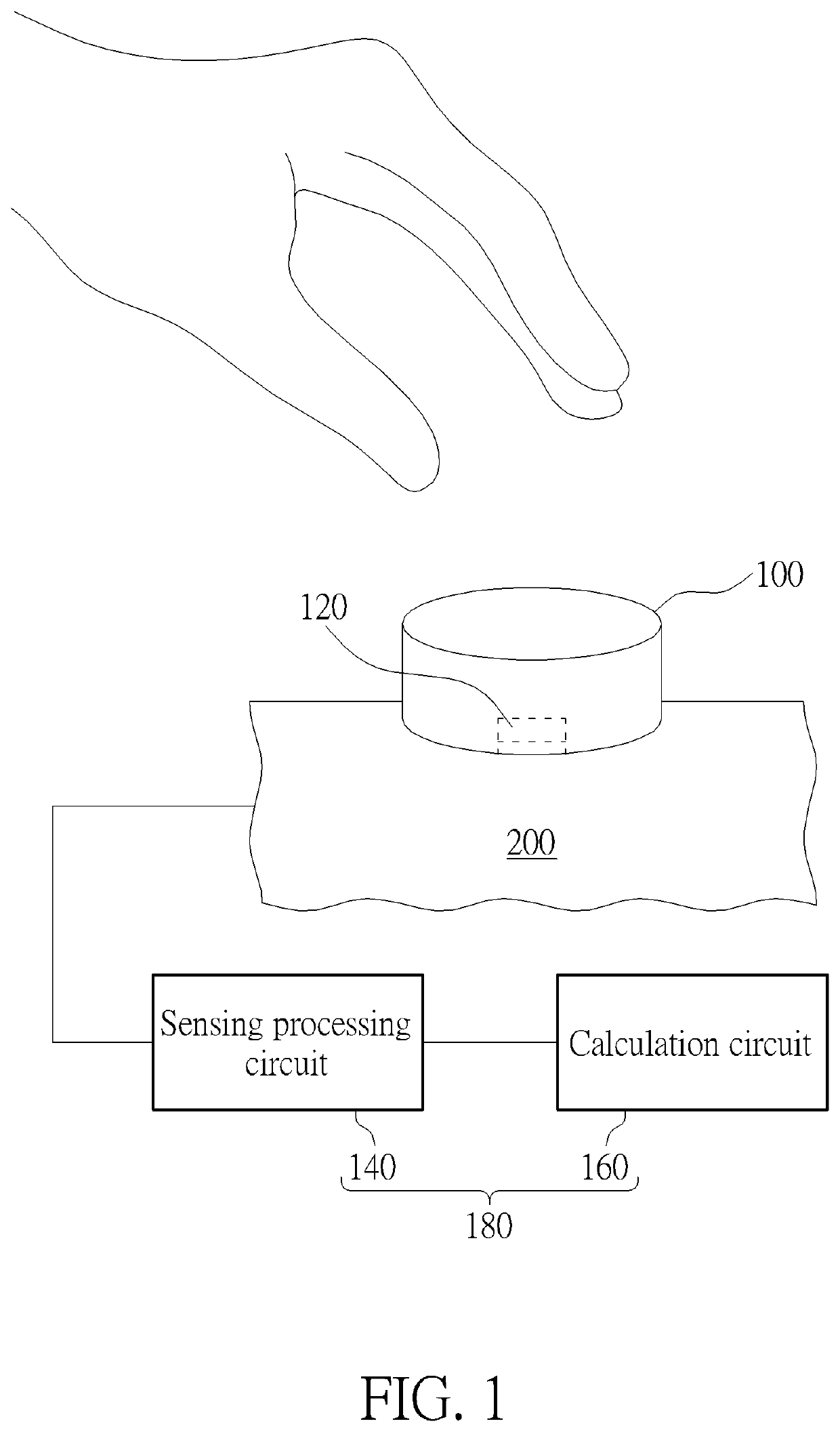
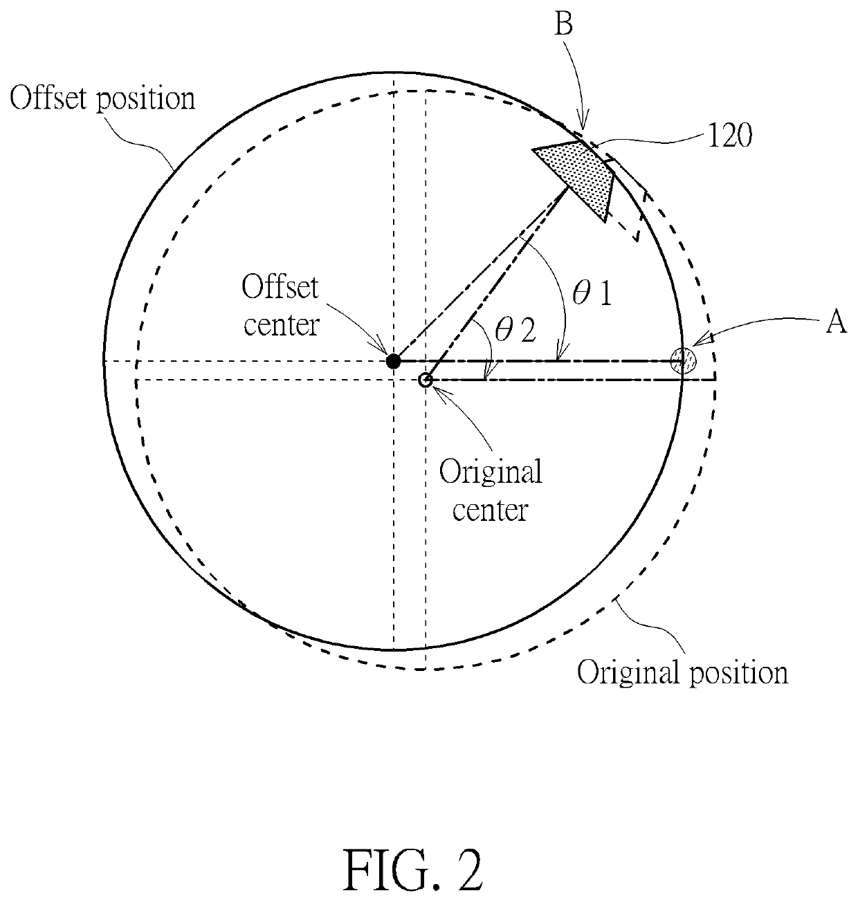
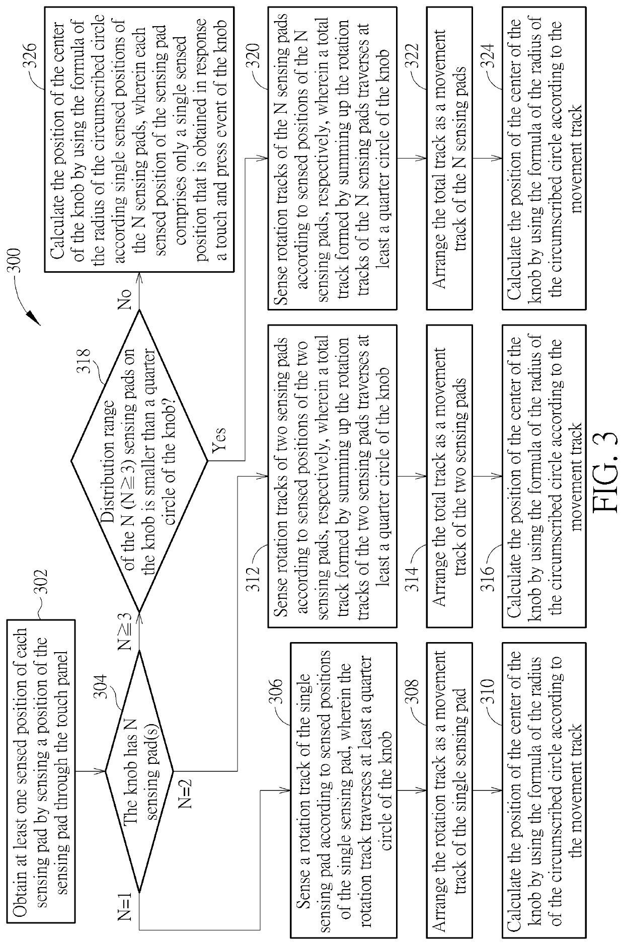
[0016]Please refer to FIG. 1. FIG. 1 is a diagram of a calibration apparatus 180 for a knob 100 applicable to a touch panel 200 according to an embodiment of the present invention. As shown in FIG. 1, the knob 100 is arranged on the touch panel 200, and comprises at least one sensing pad 120. In one embodiment, the knob 100 may comprise only a single sensing pad 120. In another embodiment, the knob 100 may comprise multiple sensing pads 120. For brevity, only one sensing pad 120 is shown in FIG. 1. Taking the knob 100 with only a single sensing pad 120 as an example, when a user operates the knob 100 by contacting the knob 100, the knob 100 forms a conductive path through the sensing pad 120. This path allows the user's finger touching the knob 100 to be connected to the touch panel 200 through the conductive path, which is equivalent to allowing the user to indirectly control the touch panel 200. In other words, when the user touches the knob 100, the touch panel 200 generates a se...


PUM


Abstract

A calibration method and a calibration apparatus for a knob applicable to a touch panel are provided. The knob includes at least one sensing pad. The calibration method includes: obtaining sensed position(s) of each sensing pad by sensing a position of the sensing pad through the touch panel; and calculating a position of a center of the knob by using a formula of a radius of a circumscribed circle according the sensed position(s) of each sensing pad.

Description

CROSS REFERENCE TO RELATED APPLICATIONS[0001]This application claims priority to U.S. Provisional Patent Application No. 63 / 186,805, filed on May 11, 2021, the disclosure of which is incorporated herein by reference in its entirety.BACKGROUND OF THE INVENTION1. Field of the Invention[0002]The present invention relates to a user interface (UI) mechanism design, and more particularly, to a calibration method for a knob applicable to a touch panel.2. Description of the Prior Art[0003]Knob devices are often used in general electronic apparatus, such as the knob for volume adjustment on an audio player, the knob for frequency adjustment on a radio and the knob for air conditioning / air volume adjustment on a car console, where many of these electronic apparatuses are equipped with a touch panel. Therefore, how to integrate the knob device and the touch panel to assist user in control has become an issue. When a touch panel is equipped with a knob, a position of the knob may be offset for ...

Claims


Application Information

Patent Timeline
IPC IPC(8): G06F3/0362G06F3/041
CPCG06F3/0362G06F3/0418G06F3/03547G06F3/0393G06F3/038
Inventor SU, CHUN-JENTSAI, CHENG-HUNGHUANG, PO-HSUANCHUANG, CHUN-KAI
Owner HIMAX TECH LTD
Learn More