Downhole hydrocarbon separator and method

a hydrocarbon separator and downhole technology, applied in the field of apparatus and methods, can solve the problems of equipment that requires power and moving components, the hydrocarbon production rate is limited, and the hydrocarbon production rate cannot sustain the hydrocarbon production to the well surface,

Inactive Publication Date: 2000-01-18
HUNTER CLIFFORD WAYNE
View PDF4 Cites 102 Cited by
  • Summary
  • Abstract
  • Description
  • Claims
  • Application Information

AI Technical Summary

Problems solved by technology

Accordingly, the hydrocarbon production rate is limited by the volume of water handled by the well fluid production equipment.
In low pressure wells, or as the subsurface well pressures decline during the producing life of a well, the reservoir pressure does not sustain hydrocarbon production to the well surface.
However, such equipment requires power and moving components subject to wear and failure.

Method used


Image

  • Downhole hydrocarbon separator and method
  • Downhole hydrocarbon separator and method
  • Downhole hydrocarbon separator and method

Examples


Embodiment Construction

The present invention provides an apparatus and method for separating hydrocarbons from other well fluids downhole in a wellbore. The invention is capable of accomplishing this functional result without moving components, is economical to construct, and is adaptable to wells having different orientations and characteristics.

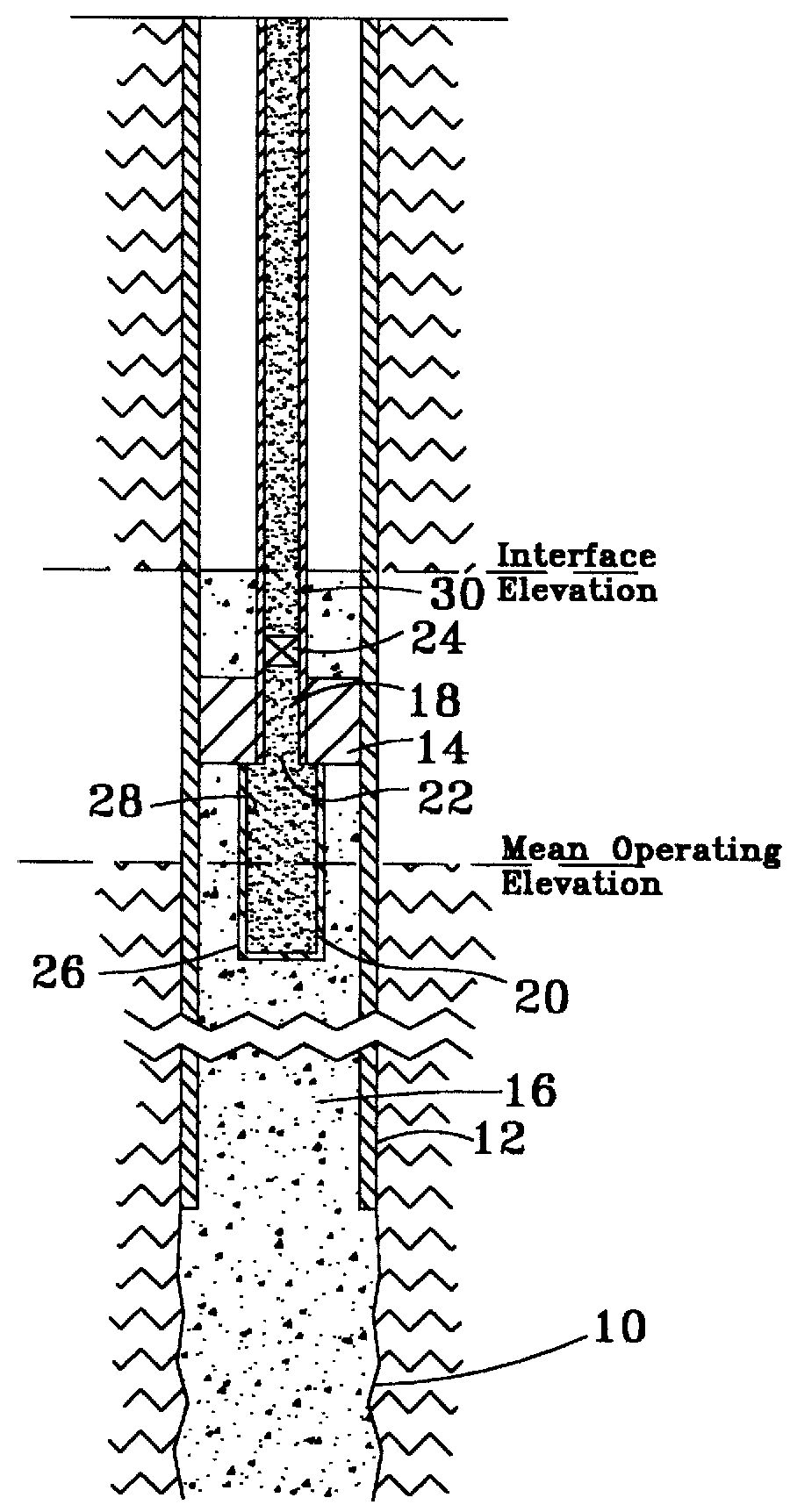
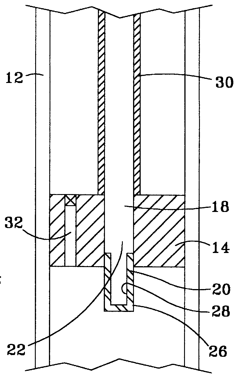
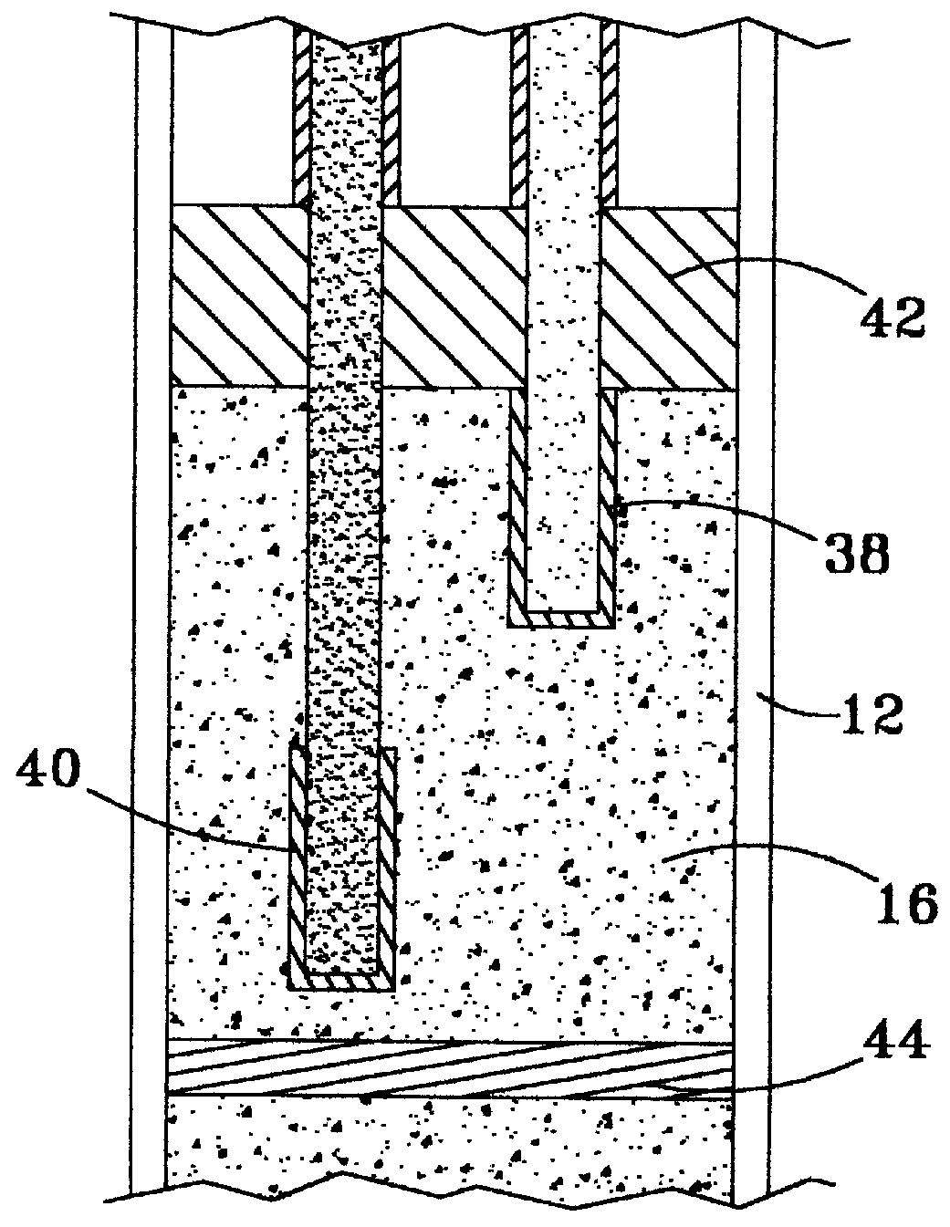
FIG. 1 illustrates a conventional wellbore 10 having casing 12 positioned within wellbore 10. A body such as packer 14 is positioned within casing 12 with conventional setting procedures. Well fluid 16 is located within casing 12 below packer 14, and flows from at least one hydrocarbon producing geologic formation below packer 14. As previously described, well fluid 16 can comprise numerous compounds such as water, oil, gas, solids, and other liquids and fluids. The invention is applicable to conventional vertical wells and to slant hole, deviated and horizontal wells. As used herein, the phrase "above the packer" refers to the region between packer 14 and the su...


PUM


Abstract

An apparatus and method of separating hydrocarbons from water and other well fluids produced from a reservoir. A controlled permeability filter selectively permits the flow of gas, oil and other hydrocarbons while restricting water flow through the filter. The permeability of certain gases or liquids through the filter can be controlled by adjusting the pressure differential across the filter. In one embodiment of the invention, the pressure differential can be selected by adjusting the filter location within a fluid column within the wellbore. In other embodiments of the invention, multiple filters can be positioned in the wellbore, and the permeability of a filter can be adjusted to control the passage of hydrocarbons therethrough.

Description

BACKGROUND OF THE INVENTIONThe present invention relates to an apparatus and method for separating hydrocarbons from fluids in a well. More particularly, the present invention relates to an apparatus and method for controlling such separation by the relative permeability between the hydrocarbons and well fluids.Hydrocarbons such as oil and gas are produced from subsurface reservoirs. The reservoirs also contain water and other well fluids located in the interstitial pore space in the reservoir formations. In many wells, the water volume substantially exceeds the relative volume of hydrocarbons. Accordingly, the hydrocarbon production rate is limited by the volume of water handled by the well fluid production equipment. As the well fluids are produced, the excess water and hydrocarbons are typically separated at the well surface, and the excess water is discharged or reinjected into subsurface formations.When a wellbore perforates the reservoir and a perforated tubing is positioned w...

Claims


Application Information

Patent Timeline
Patent Type & Authority Patents(United States)
IPC IPC(8): E21B43/02E21B43/08E21B43/34E21B43/38
CPCE21B43/08E21B43/38
Inventor HUNTER, CLIFFORD WAYNE
Owner HUNTER CLIFFORD WAYNE
Why Eureka
Try Eureka