

Vehicle seat provided with a device for protecting the neck in the event of impact from behind
a technology for protecting the neck and seat back, which is applied in the direction of seat, pedestrian/occupant safety arrangement, safety belt, etc., can solve the problems of rearward pivoting of the entire seat back, running the risk of injuring passengers situated behind the seat back, and running the risk of exposing the seat passenger to an impact. , to achieve the effect of reducing the drawbacks
- Summary
- Abstract
- Description
- Claims
- Application Information
AI Technical Summary
Benefits of technology
Problems solved by technology
Method used
Image

Examples
first embodiment
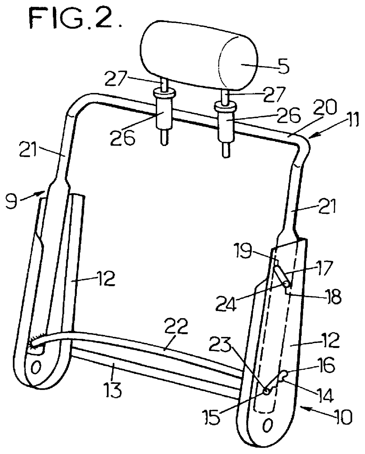
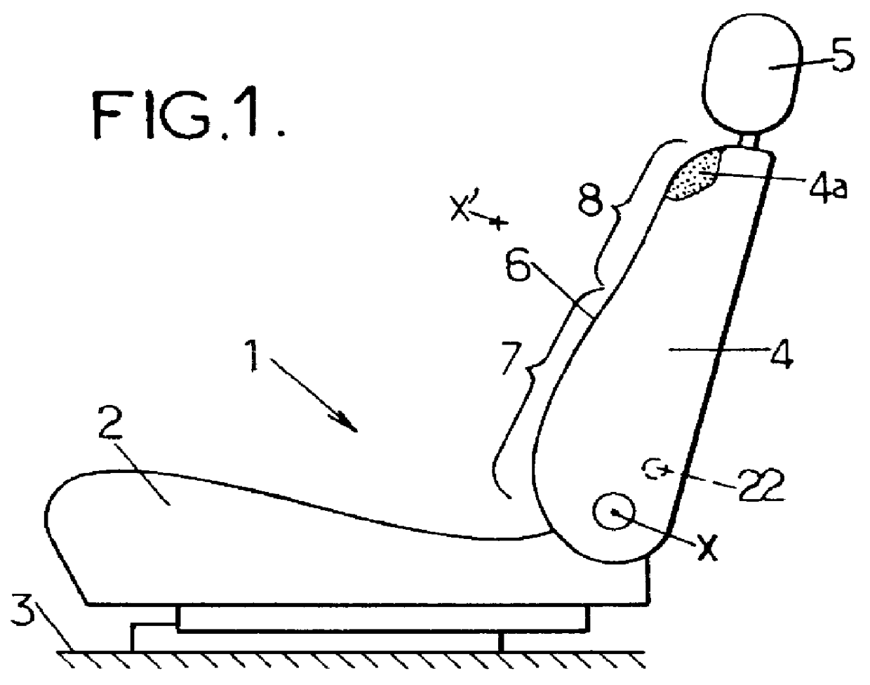
To this end, as shown in FIG. 2 for the invention, the strength-member 9 of the seat-back is made up of two portions that can be moved relative to each other, specifically a lower portion 10 pivotally mounted to the seat proper about the transverse axis X and secured to the lower region 7 of the front face of the seat-back, and secondly an upper portion 11 pivotally mounted on the lower portion 10 about a virtual pivot axis X' (FIG. 1) and which is secured to the upper region 8 of the front face of the seat-back.
In the particular example considered here, the lower portion 10 of the seat-back strength-member comprises two vertical side plates 12 pivotally mounted to the seat proper 2 about the transverse axis X and interconnected by a lower cross-member 13.
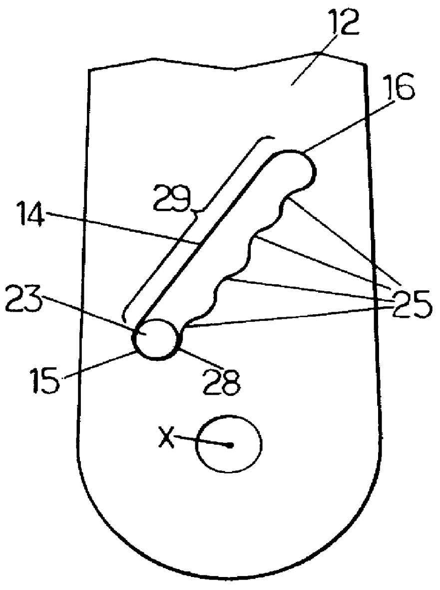
The side plates 12 have respective lower slots 14 disposed in corresponding positions on either side of the seat-back, and each sloping upwards and rearwards from a respective first end 15 to a respective second end 16.
In addition,...
second embodiment
In the invention, as shown in FIGS. 7 to 9, the lower slots 14 do not have an enlarged portion 28 and a narrower portion 29, but instead one of the lower slots 14 is provided with a set of teeth 30 forming one of the longitudinal edges of said slot.
In addition, the pivot 23 which moves along the slot 14 includes a rotary member having two fingers 31 which extend parallel to the axes X and X' and which can be rotated by a knob 32.
These two fingers 31 penetrate into a socket 33 secured to one of the side branches 21 and to the cross-member 22 of the upper portion 11 of the seat-back strength-member, so that any displacement of the fingers 31 along the slot 14 gives rise to corresponding angular displacement of the upper portion 11 of the seat-back strength-member.
In addition, a resilient metal wire 34 mounted on the side plate 12 which includes the toothed slot 14, bears continuously against the socket 33 so as to urge the fingers 31 into the set of teeth 30.
The set of teeth 30, the f...
third embodiment
In the invention as shown in FIGS. 10 to 12, all of the slots 14 and 17 are free from any ridges, and the pivot 23 in one of the slots 14 is secured to a crank-like link 36 provided with a rack 37 meshing with a gearwheel 38.
The gearwheel 38 is pivotally mounted on the corresponding side plate 12, and it is coupled to a non-reversible transmission 39 of conventional type, said transmission itself being controlled by a rotary knob 40.
The link 36, its rack 37, the gearwheel 38, the transmission 39, and the knob 40 thus constitute a non-reversible drive mechanism 41 serving to vary the distance between the gearwheel 38 and the pivot 23 by acting on the knob 40.
It is thus possible to move the pivot 23 along the corresponding slots 14 between:
firstly the first end 15 of said slot 14, corresponding to the above-mentioned first angular position for the upper portion 11 of the seat-back strength-member (FIG. 11);
secondly the second end 16 of the slot 14, corresponding to the second above-me...
PUM
 Abstract
Description
Claims
Application Information