Method and apparatus for controlling latency and jitter in shared CSMA/CD (repeater) environment

a technology of csma/cd and control method, applied in electrical apparatus, digital transmission, data switching network, etc., can solve problems such as packet drop, transmitter loss of backoff time, and difficulty in controlling latency and jitter in shared ethernet environmen

Inactive Publication Date: 2000-02-15
HEWLETT PACKARD DEV CO LP
View PDF5 Cites 88 Cited by
  • Summary
  • Abstract
  • Description
  • Claims
  • Application Information

AI Technical Summary

Problems solved by technology

While collisions are a necessary part of ethernet traffic control, they can be undesirable because after each collision, an ES experiencing collision will follow the ethernet protocol and enter backoff.
However, when the amount of data that a number of different transmitters wish to transmit appro

Method used


Image

  • Method and apparatus for controlling latency and jitter in shared CSMA/CD (repeater) environment
  • Method and apparatus for controlling latency and jitter in shared CSMA/CD (repeater) environment
  • Method and apparatus for controlling latency and jitter in shared CSMA/CD (repeater) environment

Examples


Embodiment Construction

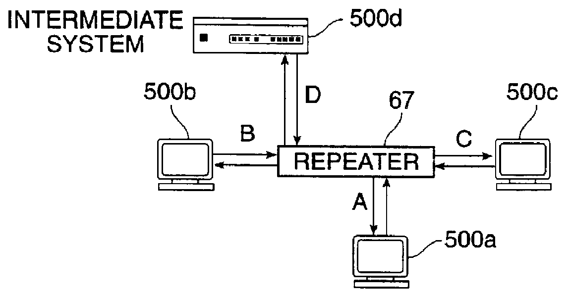
FIG. 2 is a block diagram of a repeater connected to three ESs and one IS that will be used to illustrate the invention. FIG. 5 is a block diagram representing a repeater internal structure according to one embodiment of the invention. As discussed above, according to the various methods of the invention, collisions between multiple transmitters are detected, a schedule is determined for allowing one transmitter at a time to transmit, and a transmission control is used to prevent those ESs not selected for transmission from transmitting on the shared media. A repeater or other networking device according to the invention incorporates one or more of these capabilities to improve network throughput. Various specific techniques for accomplishing these capabilities are described in the context of the following alternative specific embodiments.

FIG. 5 represents one possible arrangement of one possible device 67 in which the invention may be employed. Shown in FIG. 5 are segments 72a-d, c...


PUM


Abstract

An improved computer network and network device uses characteristics of prior art shared network protocols to control the flow of data and access to the network among a group of transmitting nodes. The invention determines which nodes wish to send data when a collision occurs by detecting and recording which nodes participated in a collision. A scheduling routine is designed to give each connected node a chance to send. A transmission control mechanism is used to prevent a subset of transmitters from transmitting while allowing one ES to transmit without experiencing a collision. The invention has a number of applications including within an improved ethernet repeater in a multimedia ethernet.

Description

Improvements to related network technology are described in co-assigned patent applications, Ser. No. 08 / 641,619, filed May 1, 1996, entitled Scalable CSMA / CD Repeater; and another filed May 16, 1997 (application no. not yet received), entitled Symmetrical Flow Control for Gigabit Ethernet Full Duplex Buffer Repeater.The current invention relates to the field of electronic circuits. More particularly, the current invention relates to improvements in networked computer environments and has particular applications to the transmission of information between digital devices over a communications medium. A very wide variety of types of computer systems and networks exist, each having variations in particular implementations. The present invention will be described with reference to particular types of systems for clarity but this should not be taken to limit the invention, and it will be apparent to those of skill in the art that the invention has applications in many different types of ...

Claims


Application Information

Patent Timeline
IPC IPC(8): H04L12/407H04L12/46H04L12/56H04L12/413
CPCH04L12/413H04L12/4625H04L12/5693H04L47/2441H04L47/263H04L47/28H04L47/58H04L47/6225H04L49/90H04L12/40013H04L47/50
Inventor SHERER, WILLIAM PAULTANG, WEN-TSUNGDALGIC, ISMAILWANG, PETER
Owner HEWLETT PACKARD DEV CO LP
Why Eureka
Try Eureka