Method and apparatus for improved control of exhaust gas temperature from a two-stroke engine

a two-stroke engine and temperature control technology, applied in machines/engines, separation processes, filtration separation, etc., can solve the problems of reducing the benefit of tuned exhaust systems, affecting the efficiency of exhaust systems, and increasing low rpm power without affecting top speed

Inactive Publication Date: 2000-02-22
LIBERTY ROSS H
View PDF4 Cites 28 Cited by
  • Summary
  • Abstract
  • Description
  • Claims
  • Application Information

AI Technical Summary

Problems solved by technology

As can be readily discerned, timing is critical since if the pressure pulse is returned too late or too early, the benefit of the tuned exhaust system is at best diminished, and at worst the exhaust system is a detriment.
The result of this process is an increase in low rpm power without affecting top speed, while the downside is that such an "on / off" approach leaves a large rpm range where the slow sonic wave speed is too slow and the fast sonic wave speed is too fast.
However, a major drawback with pulse width modulation lies in the fact that it tends to overcompensate in that the EGT (hence, the sonic wave speed) changes so quickly that in the time span of one pulse cycle, the EGT will go from too high (fast) to too low (slow) and back again.
This compromises performance.

Method used


Image

  • Method and apparatus for improved control of exhaust gas temperature from a two-stroke engine
  • Method and apparatus for improved control of exhaust gas temperature from a two-stroke engine
  • Method and apparatus for improved control of exhaust gas temperature from a two-stroke engine

Examples


Embodiment Construction

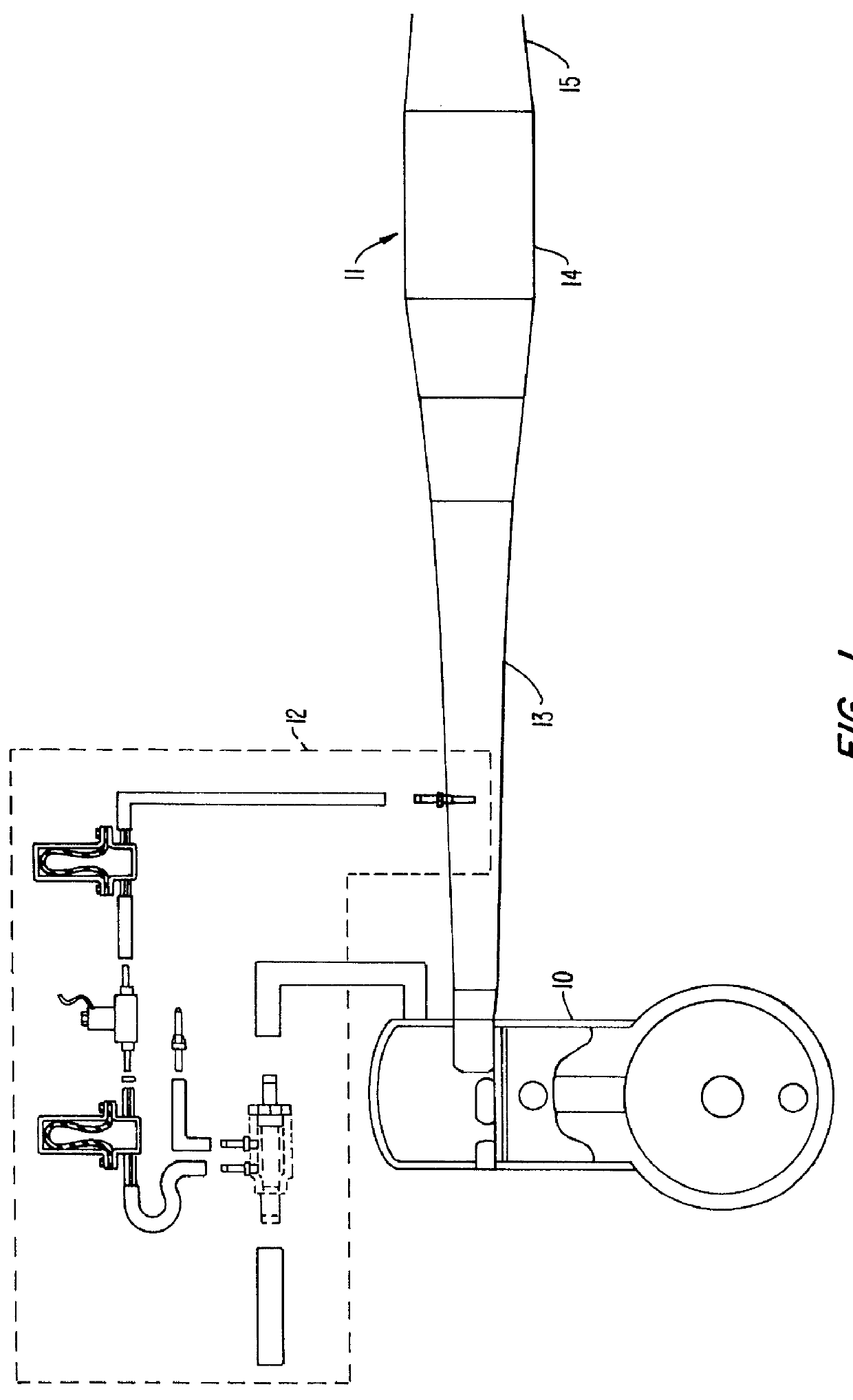
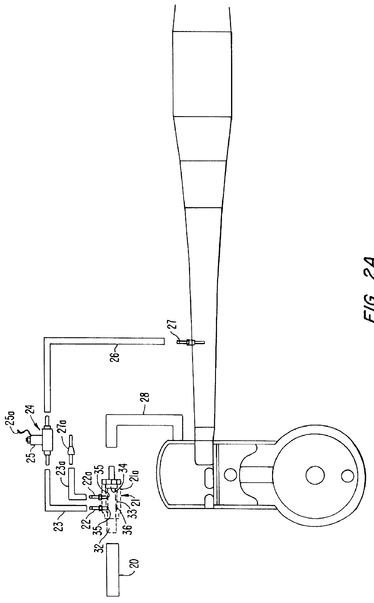
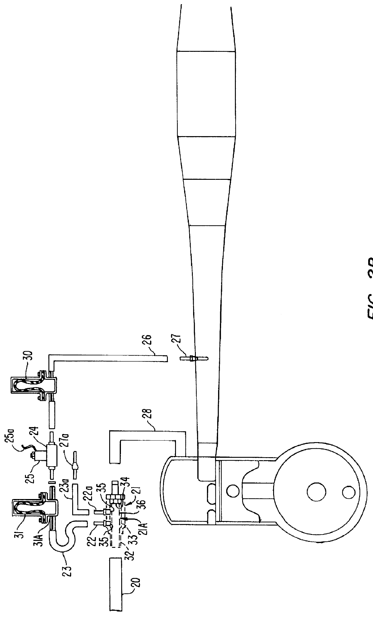
Turning to FIGS. 1, 2A and 2B, a portion of a two-stroke engine 10 is illustrated. Connected to engine 10 is an exhaust pipe 11. Also shown is an electronically controlled water injection system (ECWI) 12.

Engine 10 is a standard two-stroke engine, or two-cycle engine, as they are also sometimes referred to, commonly found in motorcycles, personal watercraft, snowmobiles, and the like. Exhaust pipe 11 has a standard design that includes an expanding and diverging section 13, an intermediate section 14, and a converging section 15. ECWI system 12 is utilized to control the exhaust gas temperature, and hence the sonic wave speed, produced by the engine within the exhaust pipe as was previously described.

ECWI system 12 includes a supply conduit 20 that is connected to a water source, i.e. a pump, a nozzle, etc., (not shown) that supplies water to ECWI system 12. Of course, any other substance suitable for cooling may be used. Supply conduit 20 is connected to a splitting junction 21 tha...


PUM

PropertyMeasurementUnit
frequencyaaaaaaaaaa
frequencyaaaaaaaaaa
frequencyaaaaaaaaaa

Abstract

An exhaust gas temperature control system for a two-stroke engine, the exhaust gas temperature control system including an electronically controlled water injection system. The electronically controlled water injection system includes a water supply conduit section for supplying water to a solenoid valve, and a spraying conduit section for injecting water into an exhaust pipe to thereby control exhaust gas temperature, and hence sonic wave speed within the exhaust pipe. A through-filter is provided as a splitting junction to provide filtered water to the electronically controlled water injection system and unfiltered water to the engine for cooling. A smoothing device in the form of an elastomer hose made of low durometer material or a pressurized bladder is included within the spraying conduit section for maintaining smooth water pressure within the water injected into the exhaust pipe. Additionally, a capturing device in the form of a pressurized bladder and check valve is provided within the supply conduit section in order to maintain ample water pressure supplied to the solenoid valve.

Description

1. Technical Field of the InventionThis invention relates to an exhaust gas temperature control system and, more particularly, to a method and apparatus for improved exhaust gas temperature control within an exhaust system of a two-stroke engine in order to improve engine performance.2. Description of the Prior ArtSmall two-stroke engines, or two-cycle engines, as they are also sometimes referred to, are commonly found in motorcycles, personal watercraft, such as JET SKIs, snowmobiles, and the like. Two-stroke engines are desirable for these types of vehicles in that they provide high output, have a low weight contained within small packaging, and are economical to produce.Basic operation of a two-stroke engine requires two piston strokes or only one revolution for each cycle. Exhaust ports in the cylinder wall are uncovered by the piston, or exhaust valves in the cylinder head are open near the end (at 60%-88%) of the expansion stroke, permitting the escape of exhaust gases and red...

Claims


Application Information

Patent Timeline
Patent Type & Authority Patents(United States)
IPC IPC(8): F01N3/04F02B75/02
CPCF01N3/04F02B2075/025Y02T10/20Y02T10/12
Inventor LIBERTY, ROSS H.
Owner LIBERTY ROSS H
Why Eureka
Try Eureka