Lockup clutch with a compensation flywheel mass at the torsional vibration damper

a technology of torsional vibration damper and clutch, which is applied in the direction of rotary clutches, fluid couplings, gearings, etc., can solve the problem that torsional vibrations of a determined order cannot be overcom

Inactive Publication Date: 2000-02-22
ZF FRIEDRICHSHAFEN AG
View PDF4 Cites 142 Cited by
  • Summary
  • Abstract
  • Description
  • Claims
  • Application Information

AI Technical Summary

Problems solved by technology

However, torsional vibrations of a determined order cannot be overcome.

Method used


Image

  • Lockup clutch with a compensation flywheel mass at the torsional vibration damper
  • Lockup clutch with a compensation flywheel mass at the torsional vibration damper

Examples


Embodiment Construction

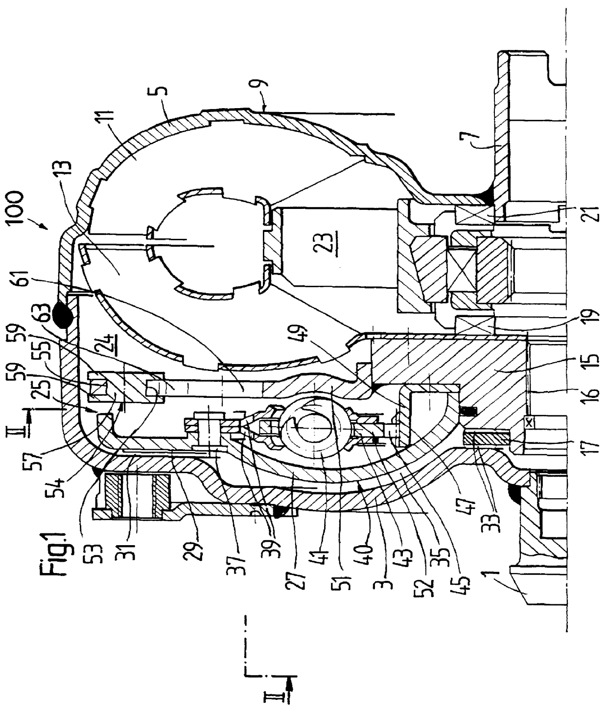
FIG. 1 shows a hydrodynamic torque converter 100 having a bearing journal 1 from which a primary flange 3 extends radially outward. The primary flange 3 is fixedly connected to an impeller shell 5 that carries a converter hub 7 at its radial inner end. The primary flange 3 and the impeller shell 5 form a converter housing 9 of the torque converter 100.

The impeller shell 5 has a vane arrangement for forming an impeller wheel 11 of the torque converter 100. The impeller wheel 11 cooperates with a turbine wheel 13 which also has a vane arrangement. The turbine wheel 13 is fastened to a turbine hub 15 which has an inner toothing 16. The turbine hub 15 is connectable with a conventionally constructed driven shaft via the inner toothing 16. For example, a driven shaft of the kind shown and described in reference DE 41 21 586 A1 which was cited above, may be used.

The turbine hub 15 is clamped between an axial bearing 17 and an axial bearing 19. The axial bearing 17 separates the turbine hu...


PUM


Abstract

A lockup clutch at a hydrodynamic torque converter is constructed with a torsional vibration damper which has a drive-side transmission element and a driven-side transmission element which is rotatable relative to the latter. Both of the transmission elements are provided with driving devices for driving elastic elements of a damping device. A carrier for a compensation flywheel mass is associated with the driven-side transmission element, wherein the carrier is connected with the turbine wheel on the one hand and with the driven-side driving device of the elastic elements on the other hand so as to be fixed with respect to rotation relative thereto and is provided at least with a cutout for receiving the compensation flywheel mass. The cutout has a guide path at least in its area of contact with the compensation flywheel mass, which guide path allows a movement of the compensation flywheel mass with at least one component perpendicular to the radial direction at the carrier.

Description

1. Field of the InventionThe present invention is directed to a lockup clutch for a hydrodynamic torque converter with a torsional vibration damper.2. Description of the Related ArtA prior art lockup clutch is disclosed by FIGS. 1 and 2 of reference DE 41 21 586 A1. This prior art lockup clutch is arranged in a hydrodynamic torque converter axially between the converter housing and the turbine wheel. The lockup clutch has a piston which is arranged so as to be rotatable and axially displaceable on a turbine hub. The lockup clutch also acts, via a rivet connection, on driving means on a drive side for elastic elements of a damping device. The lockup clutch forms, with these driving means, a drive-side transmission element of a torsional vibration damper of the lockup clutch. The elastic elements in the form of circumferential springs couple the drive-side driving means with a driven-side driving means in the form of a hub disk which is provided with an inner toothing for meshed coupl...

Claims


Application Information

Patent Timeline
Patent Type & Authority Patents(United States)
IPC IPC(8): F16H45/00F16H45/02
CPCF16F15/145F16H45/02F16H2045/0263F16H2045/0294
Inventor SUDAU, JORG
Owner ZF FRIEDRICHSHAFEN AG
Why Eureka
Try Eureka