Junction block bracket for floating connector attachment

a technology of connector attachment and junction block, which is applied in the direction of electrical equipment, incorrect coupling prevention, and coupling device connection, etc., can solve the problems of preventing expansion of the size of the junction block, increasing the number of circuits packaged in the typical junction block, and occupying space in the engine compartmen

Inactive Publication Date: 2000-02-22
YAZAKI CORP
View PDF7 Cites 94 Cited by
  • Summary
  • Abstract
  • Description
  • Claims
  • Application Information

AI Technical Summary

Problems solved by technology

As vehicle electrical systems become more complex, the number of circuits packaged in the typical junction block has increased.
However, space constraints in the engine compartment preclude expanding the size of the junction block.

Method used


Image

  • Junction block bracket for floating connector attachment
  • Junction block bracket for floating connector attachment
  • Junction block bracket for floating connector attachment

Examples


Embodiment Construction

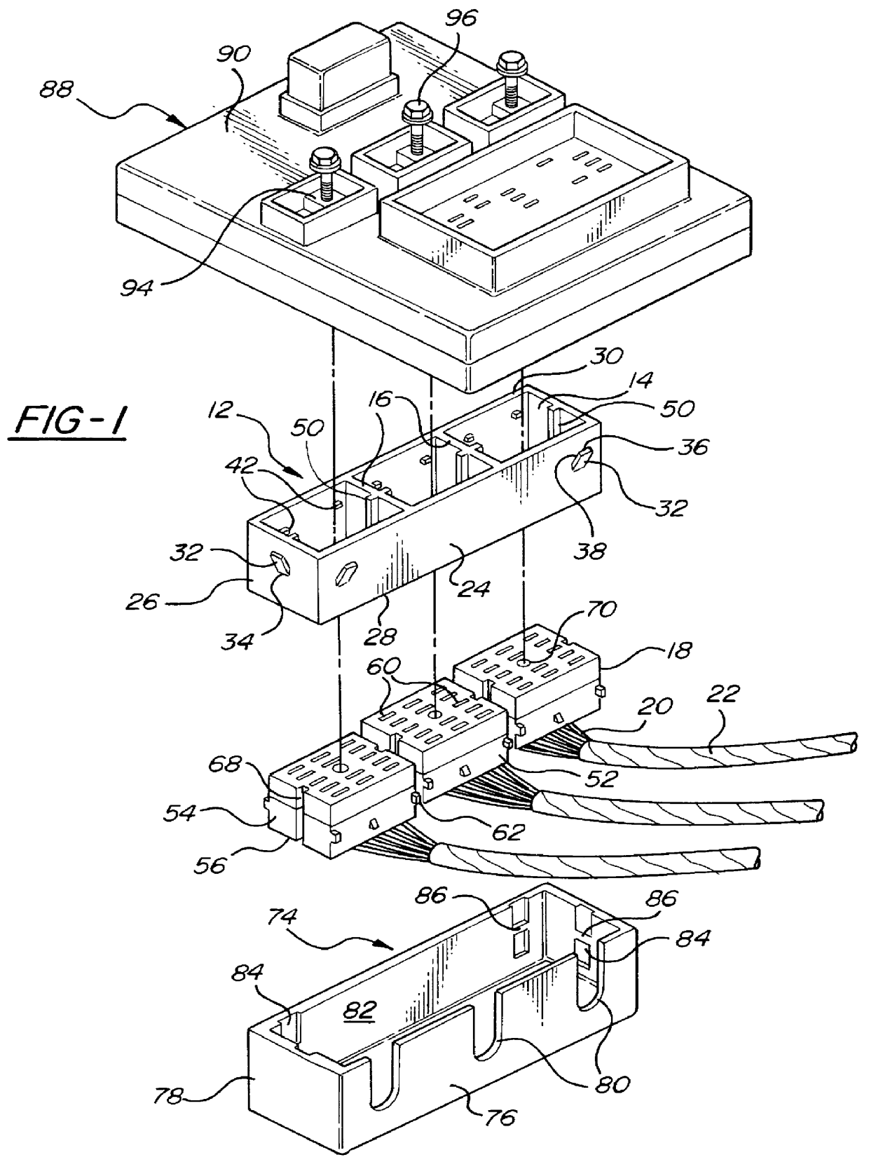
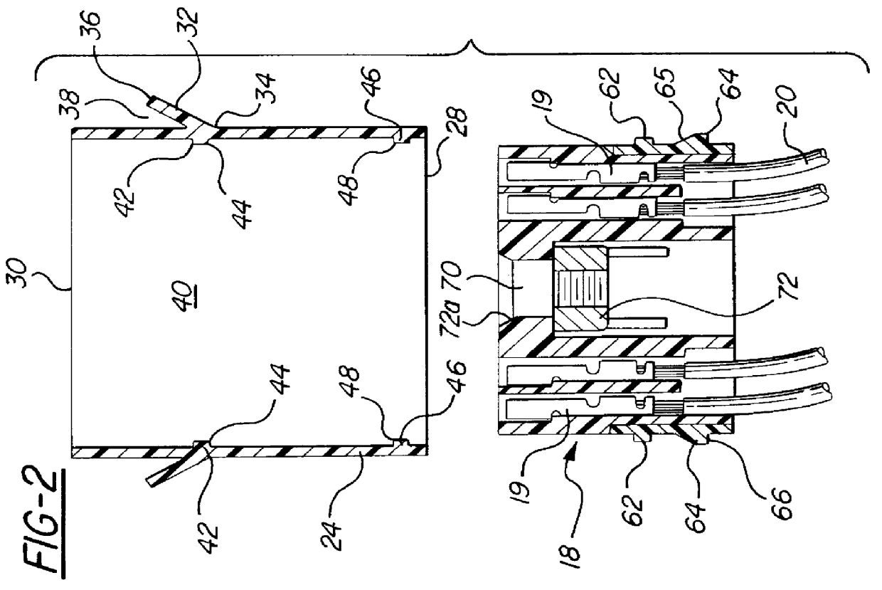
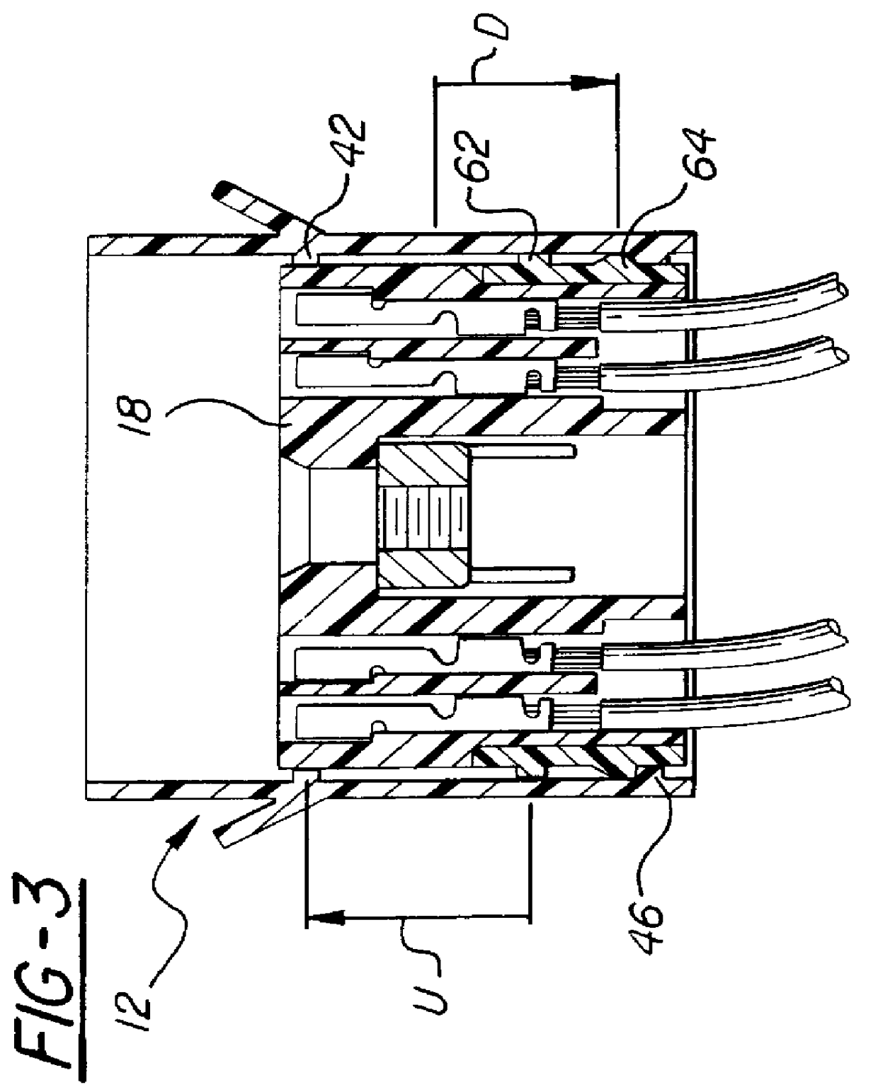
Referring now to FIGS. 1 and 2, an illustrated example of a flotation bracket 12 according to the present invention is divided into three male connector chambers 14. The ends of electrical wires 20 from harnesses 22 are terminated in male connectors 18 by electrical terminals 19 (FIG. 2) received and held in the connectors in a conventional manner.

Illustrated flotation bracket 12 is generally rectangular, with two long side walls 24 and two shorter end walls 26. The bracket has a bottom edge 28 and a top edge 30, but is otherwise open on top and bottom. Each end wall 26 has an exterior spring tab 32, and each side wall 24 includes a pair of tabs 32. The tabs have free ends 36 spaced from the end and side walls by gaps 38. The spring tabs 32 are adapted to releasably lock with mating structure in a separate lower cover 74, in a manner described below.

Flotation bracket 12 has three chambers 14. Referring to FIG. 2, each chamber includes pairs of upper stops 42 with shoulders 44 facing...


PUM


Abstract

An apparatus for securing wire harness terminal connectors to the underside of an electrical junction block in a blind assembly operation. The apparatus includes a flotation bracket with chambers for receiving the connectors in a mechanical snap-fit in which the connectors are free to float up and down over a limited range within their respective chambers. The connector-containing bracket is next placed in a lower cover, which then fits over the underside of the junction block. Bolts rotatably mounted in the junction block are located to automatically engage captive nuts held in the connectors. As the bolts are subsequently threaded through the captive nuts, the connectors are drawn up in the bracket chambers from a lower rest position to an upper electrical engagement position where the terminals in the connector are placed in electrical engagement with bus bars in the junction block. Upper stops in the chambers prevent the connectors from moving beyond the electrical engagement position and damaging parts of the junction block, bus bars, connectors and terminals.

Description

This invention relates in general to wire harness terminal connectors which mate with junction blocks, and more specifically to devices for holding the connectors while the connectors are electrically connected to components on the block.DISCUSSION OF RELATED ARTJunction blocks are typically used in automotive vehicles to streamline electrical wiring by eliminating multi-branch wiring. A junction block enables branch circuits, fuses, relays and other electrical circuit components to be consolidated in a single housing. The housing is often located within a vehicle engine compartment. Electrical connectors attached to the housing connect the circuit components through wire harnesses to various electrical devices, such as headlamps, fuel pumps, windshield wiper motors and ignition switches.As vehicle electrical systems become more complex, the number of circuits packaged in the typical junction block has increased. However, space constraints in the engine compartment preclude expandin...

Claims


Application Information

Patent Timeline
Patent Type & Authority Patents(United States)
IPC IPC(8): H01R13/621H01R13/631H01R13/514H01R13/639
CPCH01R13/6215
Inventor JENKINS, RODERICK RHYS
Owner YAZAKI CORP
Why Eureka
Try Eureka