Motion vector detector and video coder

a motion vector and detector technology, applied in the field of motion vector detector and video coder, can solve the problems of coarse granularity of motion vector detection, recognition of visual disturbance, and visual disturban

Inactive Publication Date: 2000-03-21
PANASONIC CORP
View PDF13 Cites 55 Cited by
  • Summary
  • Abstract
  • Description
  • Claims
  • Application Information

AI Technical Summary

Problems solved by technology

To the contrary, when the region is larger, the detection precision is higher, but the granularity of motion vector detection becomes coarse.
If the coding amount is limited, however, it is recognized as a visual disturbance.
In a limited coding amount, however, a quantizing error of a DC component in each

Method used


Image

  • Motion vector detector and video coder
  • Motion vector detector and video coder
  • Motion vector detector and video coder

Examples


first embodiment

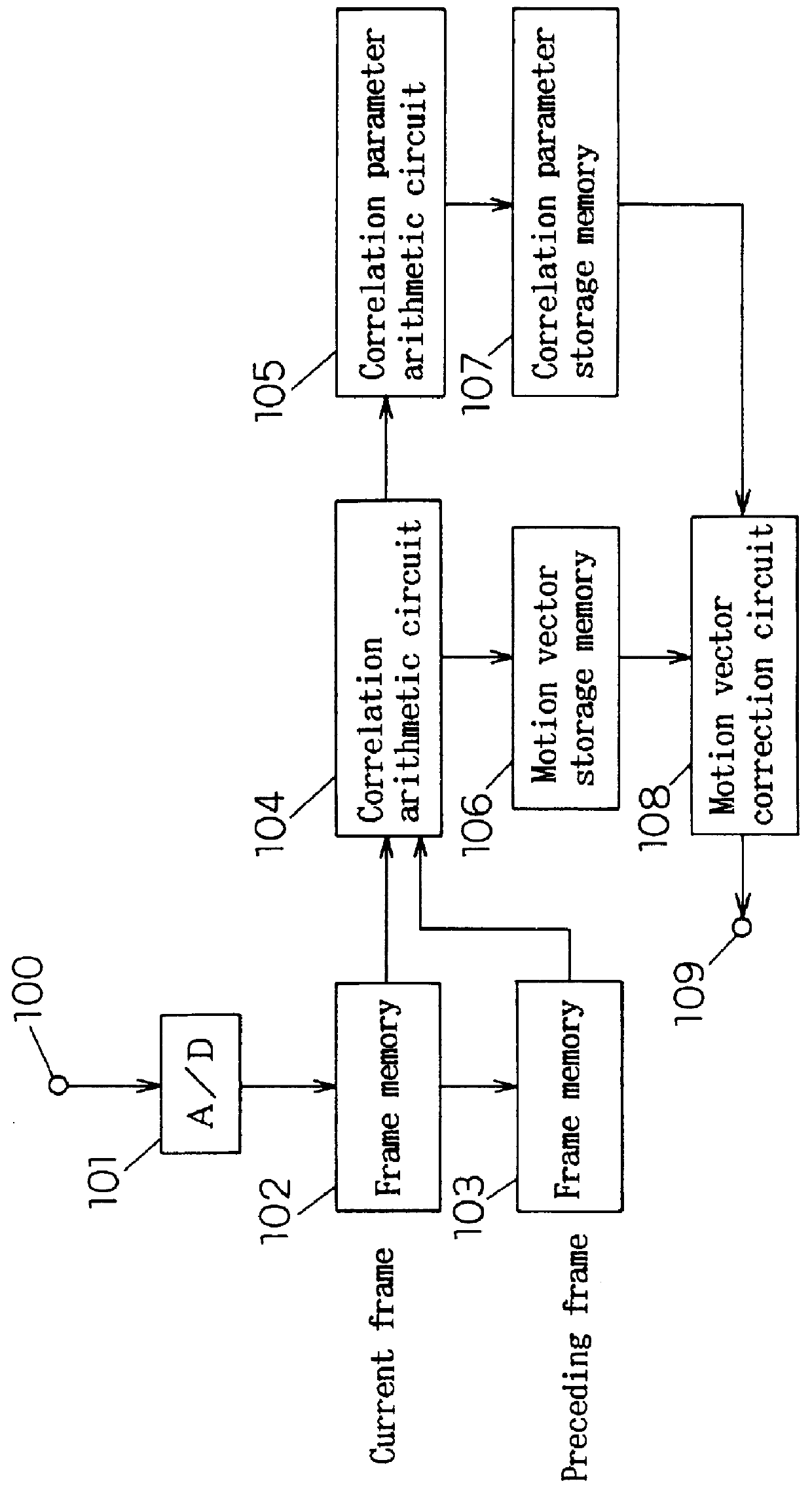
FIG. 1 is a block diagram of a motion vector detector in the invention. FIG. 9 and FIG. 10 are diagrams for explaining the block correlation processing. In FIG. 1, reference numeral 100 is a video input terminal, 101 is an A / D converting circuit for quantizing a video analog signal, 102, 103 are frame memories for storing preceding and succeeding frames of the picture, 104 is a correlation arithmetic circuit for block correlation calculation, 105 is a correlation parameter arithmetic circuit for calculating the correlation parameter from the result of block correlation calculation, 106 is a motion vector storage memory, 107 is a correlation parameter storage memory, 108 is a motion vector correcting circuit for correcting the motion vector by correlation parameter, and 109 is a motion vector output terminal. Herein, this embodiment of the invention, in which the frame memories 102, 103 compose a memory, the correlation arithmetic circuit 104 composes error arithmetic means, the corr...

second embodiment

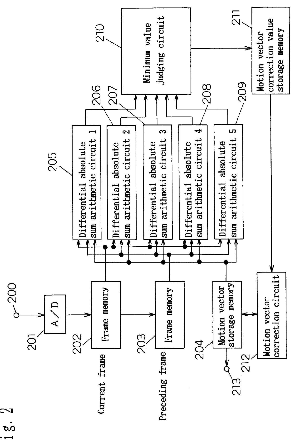
Referring now to FIGS. 2, 9 and 10, the processing procedure of the motion vector detector of the second embodiment is described below.

Different from the first embodiment, in the second embodiment, the zero vector is used as the initial estimate of motion vector, and the motion vector of each block is corrected and determined by repetition of local correlation calculation.

In this embodiment, the repeating step of this operation is expressed as s, and the estimate motion vector at that moment as (u(s), v(s)). In the motion vector storage memory 204, the motion vector of (u(s), v(s))=(0,0) in each block at step s=0 is stored. The differential absolute sum arithmetic circuit (1) 205 calculates formula 22, the differential absolute sum arithmetic circuit (2) 206 does formula 23, the differential absolute sum arithmetic circuit (3) 207 does formula 24, the differential absolute sum arithmetic circuit (4) 208 does formula 25, and the differential absolute sum arithmetic circuit (5) 209 do...

third embodiment

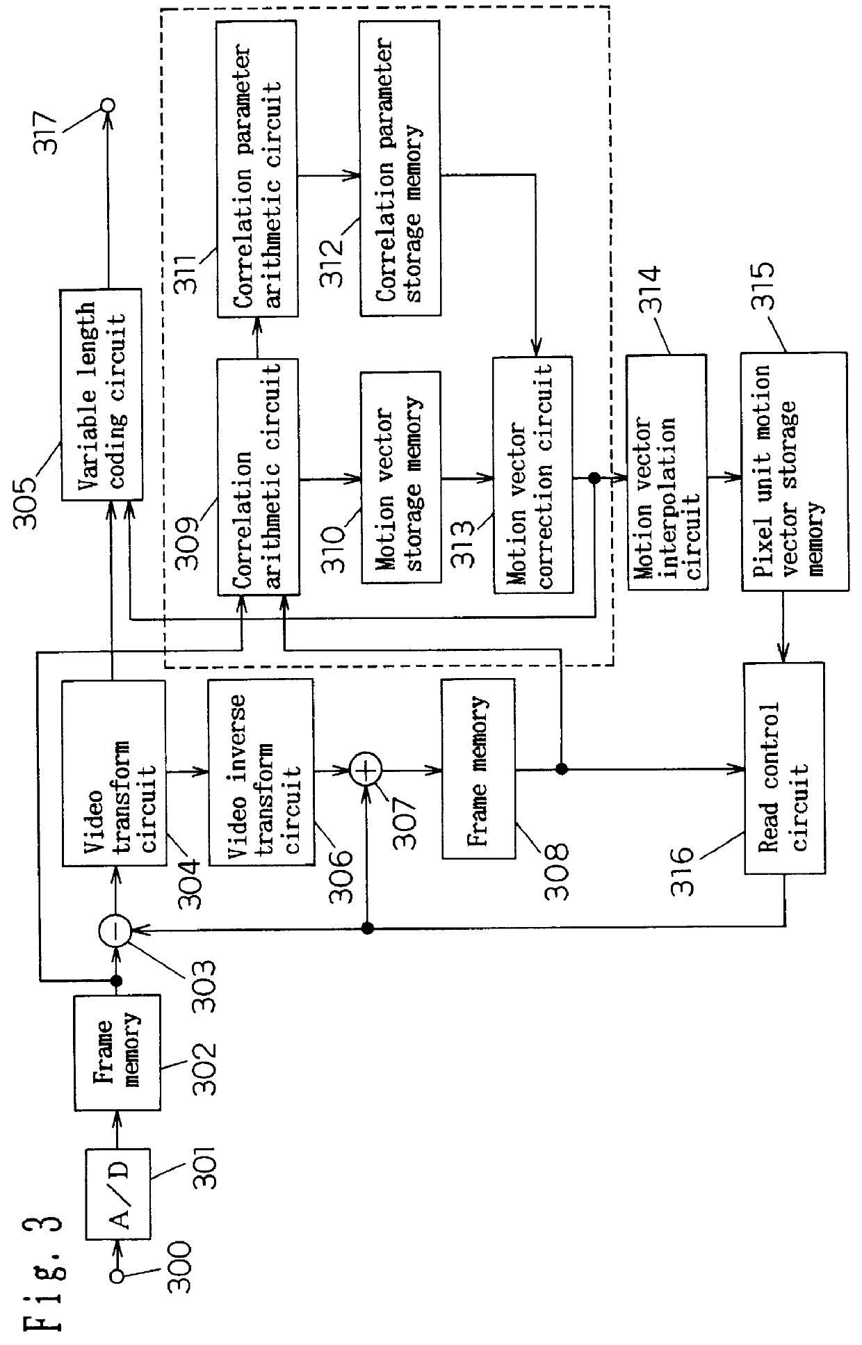
The third embodiment relates to the motion vector detector and video coder for inter-frame coding by using a motion compensated image. Same as in the first and second embodiments, the input image is composed of 144.times.176 pixels, and in the block divided into 18.times.22 pieces shown in the first embodiment, the motion vector detector for detecting its parallel move component as a motion vector is used as a motion detecting unit. The operation of the block from 309 to 313 in the broken line in FIG. 3 is same as the block shown in the first embodiment, and hence the explanation of the operation is omitted. As a result, the motion vector correction circuit 313 generates a spatially smooth motion vector. In this embodiment, by making use of the fact that this motion vector is obtained smoothly, a motion vector in the pixel unit is generated by bilinear interpolation in the motion vector interpolation circuit 314 (405) (for the decoding case, see FIG. 4, same hereinafter). This opera...


PUM


Abstract

By a motion vector correction circuit 313, a motion vector minimizing the sum of a value of the quadratic error function having a motion vector as a variable and the motion vector changing amount in neighboring blocks is determined, and it is linearly interpolated by a motion vector interpolation circuit 314 to obtain a motion vector in a pixel unit, and a motion compensated picture is generated, and a differential picture of the current frame and this motion compensated picture is divided into sub-bands by a video transform circuit 304, and only the information in the region of the large differential signal energy is coded.

Description

1. Field of the InventionThe present invention relates to a motion vector detector used in coding of image and reduction of noise, and a video coder for transmitting and accumulating images in a small coding quantity.2. Related Art of the InventionA conventional technique for detection of motion vector is described, for example, by K. FUKINUKE in "Image digital signal processing" (chapter 10, NIKKAN KOGYO SHIMBUN, 1985). Herein, the "method of minimizing the difference between consecutive images" is to determine the motion vector as the shift (a,b) for minimizing formula 1, where g.sub.t (x,y) denotes the luminance at screen position (x,y) in frame t, and R represents a block region on the screen. ##EQU1##This principle is shown in FIG. 9. The motion vector is determined as the shift (a,b) to block R' having the closest correlation with block R, in the image of frame of time t-1. In formula 1, the sum of absolute values is determined as the evaluation of correlation, but the sum of ...

Claims


Application Information

Patent Timeline
IPC IPC(8): H04N7/26G06T9/00H04N19/102H03M7/36H04N7/24H04N19/00H04N19/105H04N19/134H04N19/136H04N19/139H04N19/176H04N19/196H04N19/423H04N19/46H04N19/463H04N19/50H04N19/503H04N19/51H04N19/513H04N19/52H04N19/53H04N19/59H04N19/60H04N19/61H04N19/635H04N19/70H04N19/85H04N19/86H04N19/91
CPCH04N19/51H04N19/63H04N19/61
Inventor ETOH, MINORU
Owner PANASONIC CORP
Why Eureka
Try Eureka