Interrogator circuit arrangement

a technology of interrogator circuit and interrogator circuit, which is applied in the direction of mechanical actuation of burglar alarms, using reradiation, instruments, etc., can solve the problems of high production cost, limited suitability of tagging systems to a given application, and relatively complex and expensive transponder interrogator circuits

Inactive Publication Date: 2000-04-04
HANGER SOLUTIONS LLC +1
View PDF12 Cites 36 Cited by
  • Summary
  • Abstract
  • Description
  • Claims
  • Application Information

AI Technical Summary

Problems solved by technology

The suitability of tagging systems to a given application is at present largely limited by the cost of the interrogator circuit and tag transponder.
Whilst much time and effort has been expended in developing efficient, inexpensive semi-active tag transponders the interrogator circuits remain relatively complex and expensive.
Whilst such interrogator circuits are found to work very effectively in terms of range and robustness they have an associated problem that their production cost is high, typically of the order of a few hundred pounds.
At present, whilst the tags have very low power consumption, the interrogator, which is typically located at a fixed location and has the benefit of a mains power supply available, has a relatively high power consumption.

Method used


Image

  • Interrogator circuit arrangement

Examples


Embodiment Construction

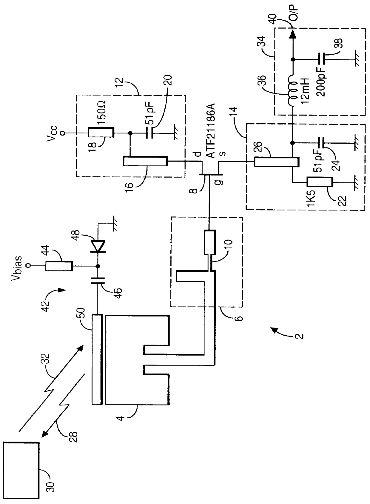
Referring to the drawing, there is shown an interrogator circuit 2 in accordance with the invention which comprises a patch antenna 4 configured for operation at 2.45 GHz. The antenna 4 is connected by a means of an impedance matching network 6 to the gate g of a field affect transistor (FET) 8. In the embodiment illustrated the FET 8 is a Gallium Arsenide FET ATF 21186A. For operation at 2.45 GHz the matching network 6 comprises a microstrip line arrangement 10 which matches the impedance of the FET 8 to that of the antenna 4 thereby ensuring the reflection coefficient, or return loss, of the antenna as seen from the FET 8 is low, typically of the order of -20 dB.

Respective bias and matching networks 12, 14 and provided at the drain d and source s of the FET 8. The bias and matching networks 12, 14 set the appropriate dc operating condition, bias condition, for the FET 8 and ensure that the FET 8 operates as a negative resistance; that is a signal applied to the gate g is reflected...


PUM


Abstract

An interrogator circuit (2) for use with a semi-passive transponder (30) of a type which reflectively modulates an incoming signal (28) is described. The circuit (2) comprises an antenna (4), a transistor (8), a matching network (6) connecting to the antenna (4) to an input of the transistor and means (12, 14) for operating the transistor such that it self-oscillates and radiates power (28) from the antenna (4) and simultaneously acts as a self-oscillating mixer to produce an output (40) which is representative of the modulation of a signal 32 received at the antenna. For an efficient conversion gain the reflection coefficient of the antenna (4) is configured to be low when the circuit is in a stable self-oscillating condition.

Description

1. Field of the InventionThis invention relates to an interrogator circuit for use in a tagging system which has tags including a semi-passive or reflective modulating transponder.2. Description of the Related ArtThe application of tagging systems using transponder circuits is becoming increasingly widespread. Tagging systems generally comprise a number of integrator circuits which are connected to a control centre by means of a communications network and a number of tags with which the interrogator can communicate typically by means of radio links. Generally an interrogator circuit is at a fixed location whilst the tags are fitted to objects which are mobile.One example of a tagging system is a road tolling system in which vehicles are fitted with a transponder (tag) which can be interrogated by interrogating circuits which are situated at toll collection points around the road network. Communication between the vehicle and the interrogating circuit provides the requisite tolling i...

Claims


Application Information

Patent Timeline
Patent Type & Authority Patents(United States)
IPC IPC(8): G06K7/00H03B5/18G01S13/00G01S13/75G01S7/28G01S7/282
CPCH03B5/1852G06K7/0008G01S7/282G01S13/756
Inventor FORSTER, IAN JAMES
Owner HANGER SOLUTIONS LLC
Why Eureka
Try Eureka