Concentric air delivery and return oven

a technology of air delivery and return oven, which is applied in the direction of domestic stoves or ranges, furnaces, heating types, etc., can solve the problems of discharging or "washing out" the collimated jet of air

Inactive Publication Date: 2000-04-11
WILSON W ROBERT
View PDF4 Cites 32 Cited by
  • Summary
  • Abstract
  • Description
  • Claims
  • Application Information

AI Technical Summary

Benefits of technology

This process produces a plurality of areas of low pressure, at least one of the areas of low pressure being adjacent to and encircling each of the plurality of tubes and spaced from the outlet of each tube wherein spent air is drawn toward the area of low pressure encircling the tube after the stream impinges the product and before the spent air flows to influence the flow of air toward the product in any other stream. Air from each tube has an independent air return path and adjacent air streams do not influence air flow from another tube. Air flow from each tube is balanced and does not disturb the integrity of other air streams.

Problems solved by technology

This tends to disrupt or "wash out" the collimated jets of air.

Method used


Image

  • Concentric air delivery and return oven
  • Concentric air delivery and return oven
  • Concentric air delivery and return oven

Examples


Embodiment Construction

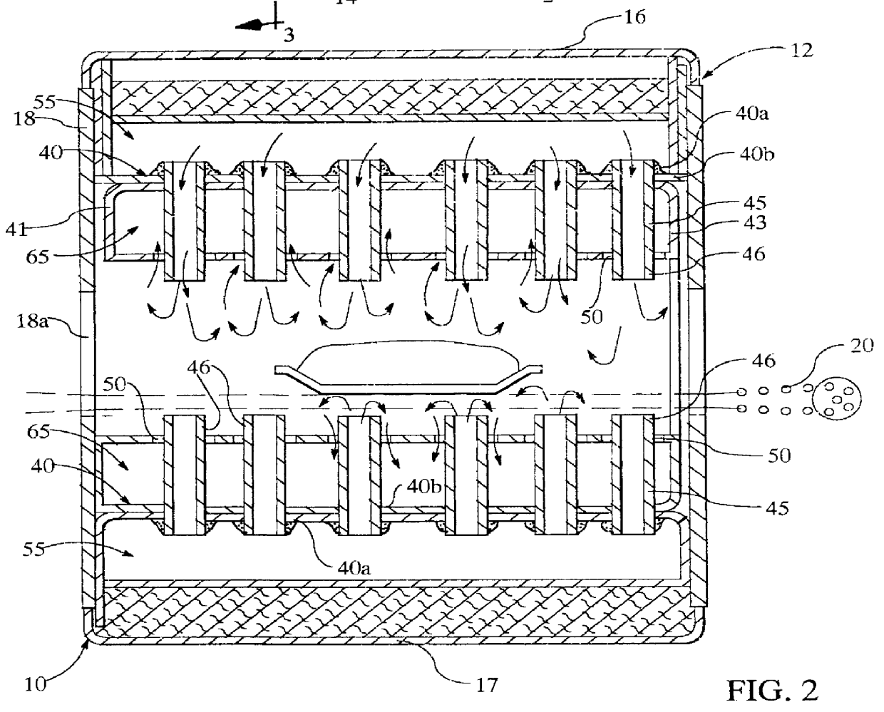
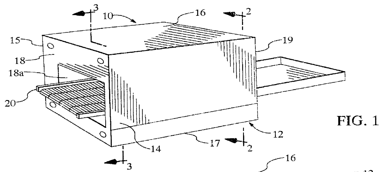
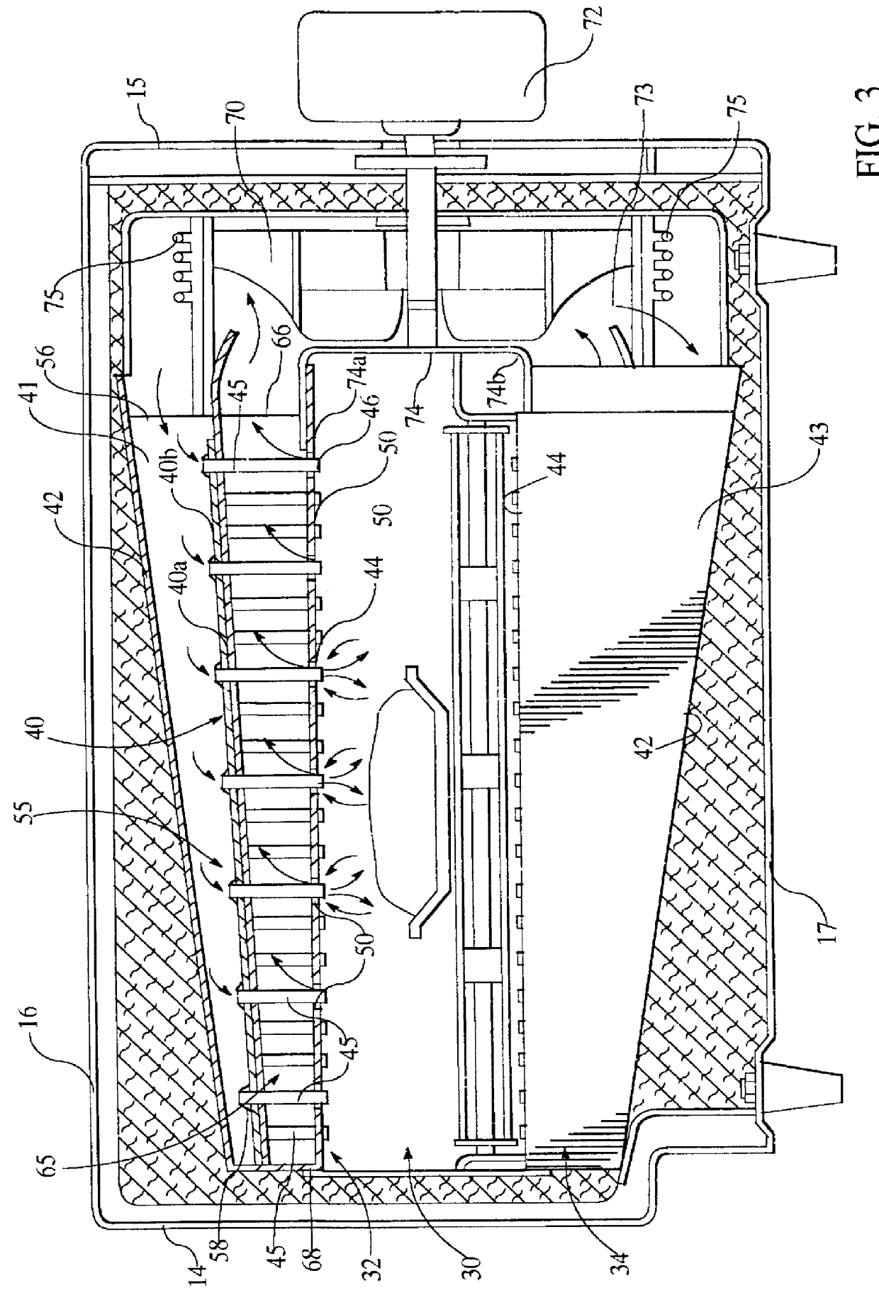
Referring to FIG. 1 of the drawing, the numeral 10 generally designates a conveyorized impingement oven which includes a cabinet 12 and a conveyor 20. Cabinet 12 has a front wall 14, rear wall 15, top wall 16, bottom wall 17 and end walls 18 and 19. As illustrated in FIGS. 1 and 2, end wall 18 has an entrance opening 18a and rear wall 19 has an exit opening 19a through which conveyor 20 extends for moving food products through an interior compartment 30 inside cabinet 12.

Conveyor 20 is preferably formed by spaced bars connected by chains driven by a motor for continuous, intermittent or reciprocating movement of a pan P through chamber 30.

For a description of details for a cabinet of the general type designated by numeral 12 in FIG. 1 of the drawing, references may be made to Kaminski et al U.S. Pat. No. 4,753,215; Henke U.S. Pat. No. 4,881,519 and Smith et al U.S. Pat. No. 5,131,841. Each of these patents disclose conveyorized impingement ovens.

Referring to FIGS. 1 and 2 of the dra...


PUM


Abstract

An impingement heat transfer device for transferring heat between a stream of temperature controlled air and a product wherein an air supply duct and an air return duct have a common wall. A tube has one end communicating with the inside of the air supply duct and another end extending through an opening in the air return duct. Air is circulated to reduce pressure in the air return duct and increase pressure in the air supply duct such that a stream of air flows through and out of the tube and spent air is drawn through the opening encircling the tube into the air return duct.

Description

The invention disclosed herein relates to impingement heat transfer apparatus for preparing food.BACKGROUND OF INVENTIONPizzas and other fast food products are generally cooked in ovens to bake the crust and to bake, heat, and melt the toppings. One style of pizza oven is a deck oven that uses radiant and conductive heat for cooking. Typically, the required baking time in a deck oven would be in a range between about 15 and 25 minutes.An impingement oven uses mostly convection to heat the pizza, as well as some heat of conduction. The newer pizza ovens typically are impingement ovens which move the pizzas through the oven on conveyors while others are equipped with rotating turntables for moving the pizza relative to air streams that impinge the pizza.An impingement oven is described in U.S. Pat. No. 4,679,542 to Don Paul Smith. These ovens, which are a special type of forced convection oven using columnated heated air to impact the pizza, have increased heat transfer capabilities a...

Claims


Application Information

Patent Timeline
Patent Type & Authority Patents(United States)
IPC IPC(8): F24C15/32A21B1/24
CPCA21B1/245A21B1/48
Inventor WILSON, W. ROBERT
Owner WILSON W ROBERT
Why Eureka
Try Eureka