High conductance plasma containment structure

a plasma containment and high conductance technology, applied in the field of high conductance plasma containment structure, can solve the problems of low conductance, small holes tend to clog, and the application of magnetic confinement to many industrial applications, and achieve excellent plasma confinement properties

Inactive Publication Date: 2000-04-18
GOOGLE LLC
View PDF11 Cites 70 Cited by
  • Summary
  • Abstract
  • Description
  • Claims
  • Application Information

AI Technical Summary

Benefits of technology

is to provide a barrier useful in systems that has excellent plasma confinement properties even when a film is being deposited on the barrier.

Problems solved by technology

Magnetic confinement has strong limitations in its application to many industrial applications.
However, utilizing such small holes in the physical barrier has been found to lead to low conductance, particularly when the molecular mean free path is similar to or longer than the dark space.
Further, these small holes tend to clog in the presence of a depositing chemistry such as is typically used in selective etching.
This clogging not only restricts the useful lifetime of the chamber but creates continually changing process conditions which can reduce process yields.

Method used


Image

  • High conductance plasma containment structure
  • High conductance plasma containment structure
  • High conductance plasma containment structure

Examples


Embodiment Construction

)

In describing the preferred embodiment of the present invention, reference will be made herein to FIGS. 1-10 of the drawings in which like numerals refer to like features of the invention. Features of the invention are not necessarily shown to scale in the drawings.

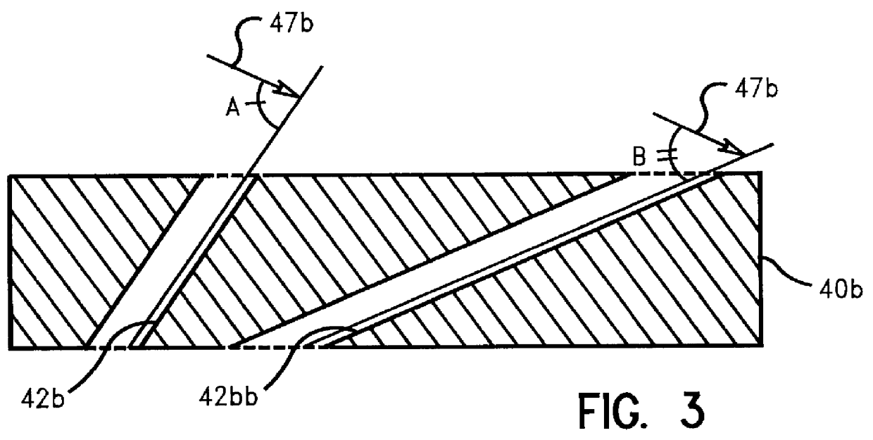
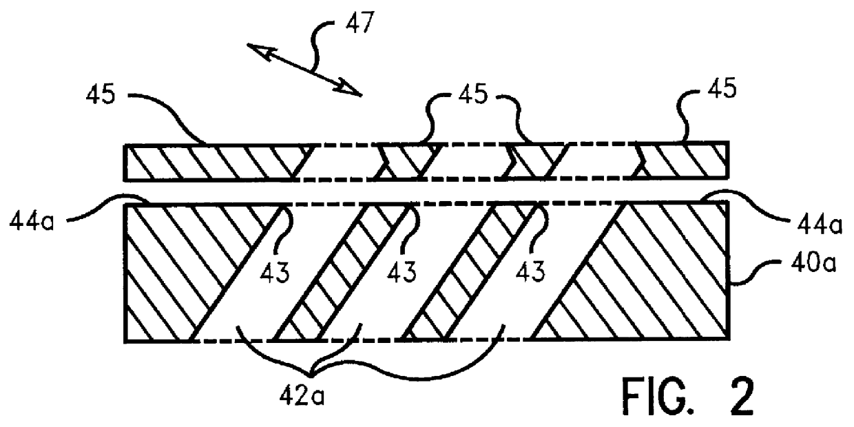
The present invention is useful for various plasma reactors which generate and contain an active plasma for depositing layers of materials, such as polymeric films, or for etching, or a combination of film deposition and etching or surface modification, etc. In the preferred embodiment, the present invention is used in reactive ion etching chambers for processing semiconductor wafers. In accordance with the teachings of this invention a barrier such as a plate is placed along the desired boundary between the plasma region and the remainder of plasma reactor chamber, such as a RIE chamber region, to be free of plasma to contain the plasma. This containment boundary may be flat or curved as desired in accordance with the p...


PUM

PropertyMeasurementUnit
angleaaaaaaaaaa
angleaaaaaaaaaa
widthaaaaaaaaaa

Abstract

Plasma containment is achieved within a region by a containment plate while gas is allowed to flow through this region by openings in the plate. The openings in the plate are larger in two of the cross-sectional dimensions parallel to the plate surface than the thickness of the dark space or plasma sheath. This plasma containment plate allows high conductance for conditions including those of long molecular mean free path and thick material deposits on the interior chamber of the plasma reactor.

Description

1. Field of the InventionThe present invention relates to a structure utilized to contain a plasma and / or electromagnetic field within a desired space while maintaining high conductance across the structure and permitting gas flow through the structure.2. Description of Related ArtPlasma processing is often used under circumstances where it is beneficial to restrict the presence of the plasma to a certain region in the chamber while maintaining the ability to flow gasses through the plasma containing region. Several methods of plasma containment are currently in practice, including magnetic confinement, inertial confinement and confinement by solid or nearly barriers. Inertial confinement works only for short periods of time and has been shown useful only in power generating and explosive devices. Magnetic confinement has strong limitations in its application to many industrial applications. Because of the shortcomings of inertial and magnetic confinement systems, industrial plasma ...

Claims


Application Information

Patent Timeline
Patent Type & Authority Patents(United States)
IPC IPC(8): H01J37/32H01L21/205H01L21/302H05H1/16H01L21/3065H05H1/46
CPCH01J37/32834H01J37/32623H01J37/32449H01J2237/3341
Inventor WALKO, II, JOSEPH PHILIP
Owner GOOGLE LLC
Why Eureka
Try Eureka