Efficient plasma containment structure

a plasma containment and efficient technology, applied in the field of efficient plasma containment structure, can solve the problems of low conductance, small holes tend to clog, and the application of magnetic confinement to many industrial applications, and achieve excellent plasma confinement properties

Inactive Publication Date: 2001-04-24
IBM CORP
View PDF13 Cites 70 Cited by
  • Summary
  • Abstract
  • Description
  • Claims
  • Application Information

AI Technical Summary

Benefits of technology

is to provide a barrier useful in systems that has excellent plasma confinement properties even when a film is being deposited on the barrier.

Problems solved by technology

Magnetic confinement has strong limitations in its application to many industrial applications.
However, utilizing such small holes in the physical barrier has been found to lead to low conductance, particularly when the molecular mean free path is similar to or longer than the dark space.
Further, these small holes tend to clog in the presence of a depositing chemistry such as is typically used in selective etching.
This clogging not only restricts the useful time between cleaning of the chamber but creates continually changing process conditions which can reduce process yields.

Method used


Image

  • Efficient plasma containment structure
  • Efficient plasma containment structure
  • Efficient plasma containment structure

Examples


second embodiment

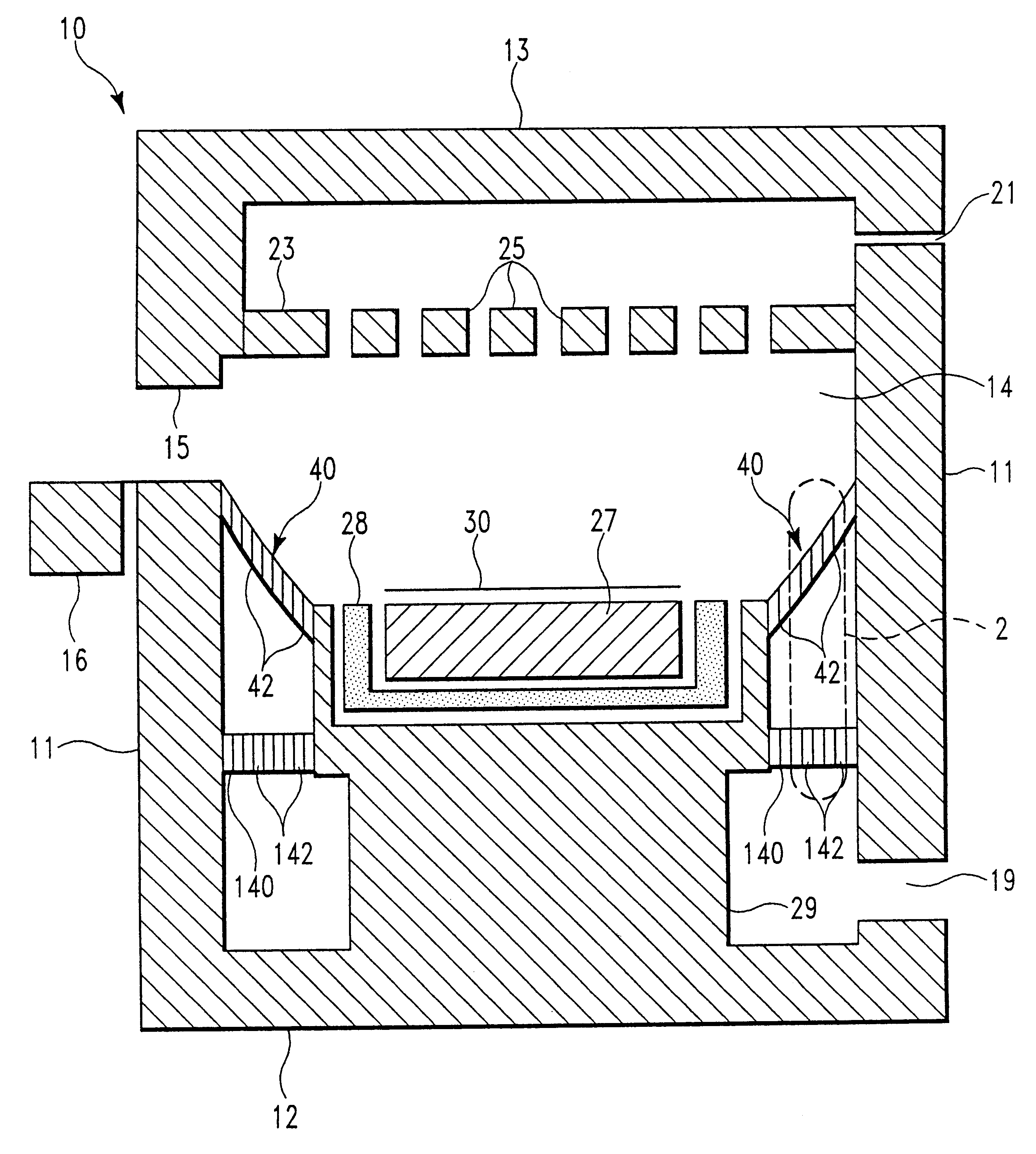
A second embodiment is illustrated in FIGS. 3-5 in which the function of the upper and lower containment plates described above are joined in a single containment plate. It is envisioned that the plates 40 and 140 shown in FIG. 1 and 2 may be replaced by a single plate 40e having an upper and lower portion.

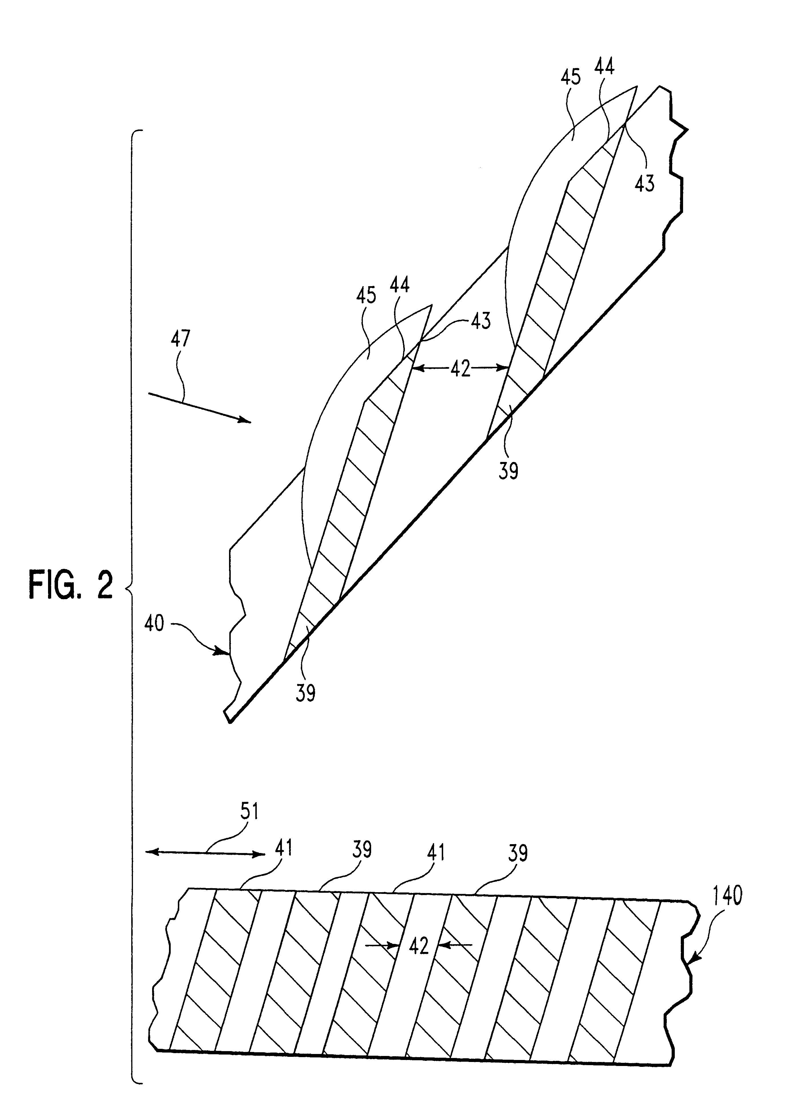
FIG. 3 depicts a bottom plan view (the side away from the active plasma) of the containment plate 40e made in accordance with the present invention for use around a cathode and workpiece in a RIE chamber. Plate 40e may be made of aluminum with an anodized coating of about 50 microns thickness plate 40e has a thickness of about 6 mm and has a series of tall rings 39a and short rings 41a forming between adjacent ones annular openings 42d in the lower portion a width of 1.4 mm at an angle of 60.degree. from horizontal and in the upper portion a width of 3.6 mm. As can now be realized, this configuration creates a wider spacing distance between ring 39a and wider openings in the upper...


PUM

PropertyMeasurementUnit
angleaaaaaaaaaa
angleaaaaaaaaaa
widthaaaaaaaaaa

Abstract

Plasma containment is achieved within a region by a containment plate while gas is allowed to flow through this region by openings in the plate. The openings in the plate are larger in two of the cross-sectional dimensions parallel to the plate surface than the thickness of the dark space or plasma sheath. The openings of the plate are wider nearest the source of the electromagnetic energy in order to attenuate the electromagnetic fields and thereby prevent build up of deposits which would block the flow gas through the plate.

Description

1. Field of the InventionThe present invention relates to a structure utilized to contain a plasma and / or electromagnetic field within a desired space while maintaining high conductance across the structure.2. Description of Related ArtPlasma processing is often used under circumstances where it is beneficial to restrict the presence of the plasma to a certain region in the chamber while maintaining the ability to flow gasses through the plasma containing region. Several methods of plasma containment are currently in practice, including magnetic confinement, inertial confinement and confinement by solid or nearly solid barriers. Inertial confinement works only for short periods of time and has been shown useful only in power generating and explosive devices. Magnetic confinement has strong limitations in its application to many industrial applications. Because of the shortcomings of inertial and magnetic confinement systems, industrial plasma confinement is most often achieved by us...

Claims


Application Information

Patent Timeline
Patent Type & Authority Patents(United States)
IPC IPC(8): H01J37/32
CPCH01J37/32623Y10S156/916
Inventor WALKO, II, JOSEPH PHILIP
Owner IBM CORP
Why Eureka
Try Eureka