Mounting arrangement for an external gearshift mechanism of an automobile transmission

Inactive Publication Date: 2000-05-16
INA WALZLAGER SCHAEFFLER KG
View PDF5 Cites 11 Cited by
  • Summary
  • Abstract
  • Description
  • Claims
  • Application Information

AI Technical Summary

Benefits of technology

Since, as a result, the gearshift lever is stationarily articulated on the engine or gearbox casing, it has only to be assured that, when tilted, the driver's cab can pivot relative to the gearshift lever by special measures implemented on the floor of the cab. The damping means arranged according to the invention between the bearing shell and the outer ring assures that vibrational excitation caused by vibrations of the engine or the drive train cannot be transmitted to the gearshift lever. Moreover, a structurally simple and very compact combination of a gearshift lever mounting and a damping is obtained.
It is further possible to insert an elastic ring into the circumferential groove to bias the tongues radially towards the ball. This elastic ring acts as a biasing means by pressing the tongues which are configured as segments against the surface of the ball without play. Since this elastic ring is inserted in the circumferential groove and therefore supported on the wall of the groove opposite the tongues, the elastic ring does not need to be pre-stressed radially by a length expansion.
The mounting arrangement of the gearshift lever advantageously comprises further components which, on the one hand, reduce the amplitude of vibration in axial direction and, on the other hand, serve as limiters for an angle of tilt of the bearing shell and the outer ring which are vibrationally insulated from each other. For obtaining these effects, a protective cap is arranged on one end face of the outer ring with interposition of a rubber profile. This protective cap accomplishes the aforesaid effects and, in conjunction with the rubber profile also prevents a penetration of dirt particles into the mounting arrangement.
An angular ring is fixed on the opposite end face of the outer ring nearer the engine or gearbox casing with interposition of a rubber profile. One end of a folding bellows is vulcanized on the bent end of the angular ring, while a second end of the folding bellows engages into a groove of the ball-ended spindle by a bead. Together with the rubber profile, this angular ring likewise effects an axial damping of vibrations and a limitation of the angular mobility of the bearing shell and the outer ring. The folding bellows which is vulcanized on the outer ring and the diameter of whose folds may increase in the direction of its beaded end, likewise prevents the penetration of dirt particles into the mounting arrangement. Due to the special conical outer contour of the folding bellows, relatively large angles of tilt can be realized in a simple manner in the mounting arrangement without damage to the folding bellows. Pivoting movements result in a relative movement between the sealing bead and the groove in the ball-ended spindle.
According to a final feature of the invention, the angular ring surrounds the tongues in radially spaced relationship thereto. Thus, the angular ring forms a radial stop which prevents the bearing shell from disengaging from the ball under extreme axial loading.

Problems solved by technology

However, a telescoping connection of the gearshift lever to the vehicle transmission is a complicated construction and involves additional costs.

Method used


Image

  • Mounting arrangement for an external gearshift mechanism of an automobile transmission
  • Mounting arrangement for an external gearshift mechanism of an automobile transmission

Examples


Embodiment Construction

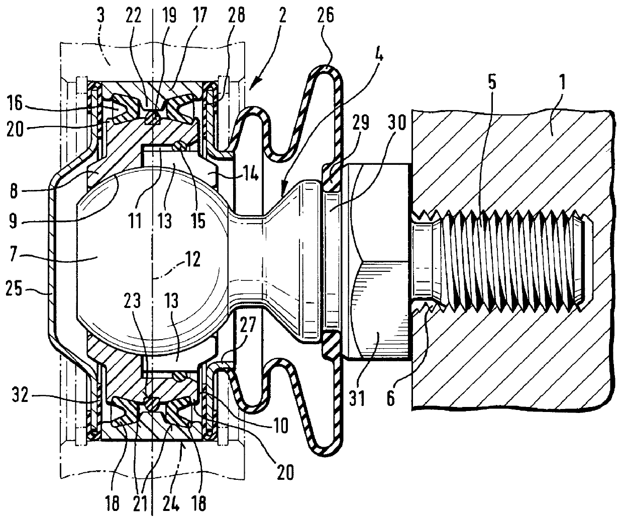
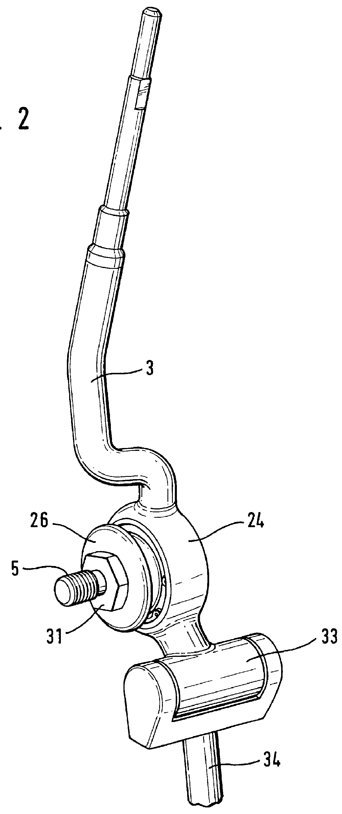
In FIG. 1, the numeral 1 identifies a portion of a housing of an internal combustion engine or of a gearbox in which a mounting arrangement 2 for a gearshift lever 3 is fixed. The mounting arrangement comprises a ball-ended spindle 4 which is fixed by a threaded portion 5 in a threaded bore 6. The ball-ended spindle 4 comprises a ball 7 for receiving on a part of its periphery, a bearing shell 8. In the view shown in FIG. 1, the bearing shell 8 is pivotable and tiltable at least about the center of the ball 7, and executes these pivoting and tilting movements on the ball 7 through a sliding surface 9.

A circumferential groove 11 starts from an end face 10 of the bearing shell 8 nearer the housing 1 and extends beyond a common central transverse plane 12 of the ball 7 and the bearing shell 8. A plurality of slits 13 spaced uniformly over the periphery of the bearing shell 8 extend in radial direction from the circumferential groove 11 and interrupt the spherical sliding surface 9 so t...


PUM


Abstract

A gearshift lever (3) is mounted on a ball-and-socket joint which is partially surrounded by a bearing shell (8) made of plastic whereby an economic mounting arrangement (2) which permits maintenance work and can prevent a transmission of vibrations to the gearshift lever (3) is achieved by the fact that the gearshift lever (3) is mounted through the bearing shell (8) on a ball (7) which is rigidly connected to an engine or gearbox casing (1), and the bearing shell (8) is connected to an outer ring (17) through damping rings (18, 19), the gearshift lever (3) being pivotally mounted on an outer peripheral surface of this outer ring through a hub (24).

Description

A mounting arrangement for a gearshift lever of an external gearshift mechanism of an automobile transmission comprising a ball-and-socket joint partially surrounded by a bearing shell made of plastic and having a concave inner peripheral surface.An external gearshift mechanism of the above type is commonly used in light and heavy utility vehicles. The gearshift lever is generally mounted on the floor of the driver's cab so that a transmission of vibrations to the gearshift lever can be largely avoided because, as a rule, the driver's cab is elastically mounted on the undercarriage of the vehicle.This type of mounting of a gearshift lever on the cab floor is described in the species-defining German Patent No. 42 21 762 A1. Since, however, for maintenance or repair work on the internal combustion engine of the utility vehicle, the driver's cab has to be tilted about a pivot axis, it is necessary either to separate the transmission linkage of the external gearshift mechanism from the ...

Claims


Application Information

Patent Timeline
IPC IPC(8): B60K20/02F16H59/04F16H59/02
CPCB60K20/02F16H59/04F16C11/0623F16H59/0208Y10T403/32557Y10T74/20165F16H2059/0269
InventorSPALTHOFF, EBERHARD
OwnerINA WALZLAGER SCHAEFFLER KG