Limited slip differential gear

Inactive Publication Date: 2000-05-16
ROUTE SIX
View PDF8 Cites 29 Cited by
  • Summary
  • Abstract
  • Description
  • Claims
  • Application Information

AI Technical Summary

Problems solved by technology

Meanwhile, in the conventional LSD having the construction set forth above, the number of parts of

Method used


Image

  • Limited slip differential gear
  • Limited slip differential gear
  • Limited slip differential gear

Examples


Embodiment Construction

A limited slip differential gear according to a preferred embodiment of the invention is now described with reference to the attached drawings.

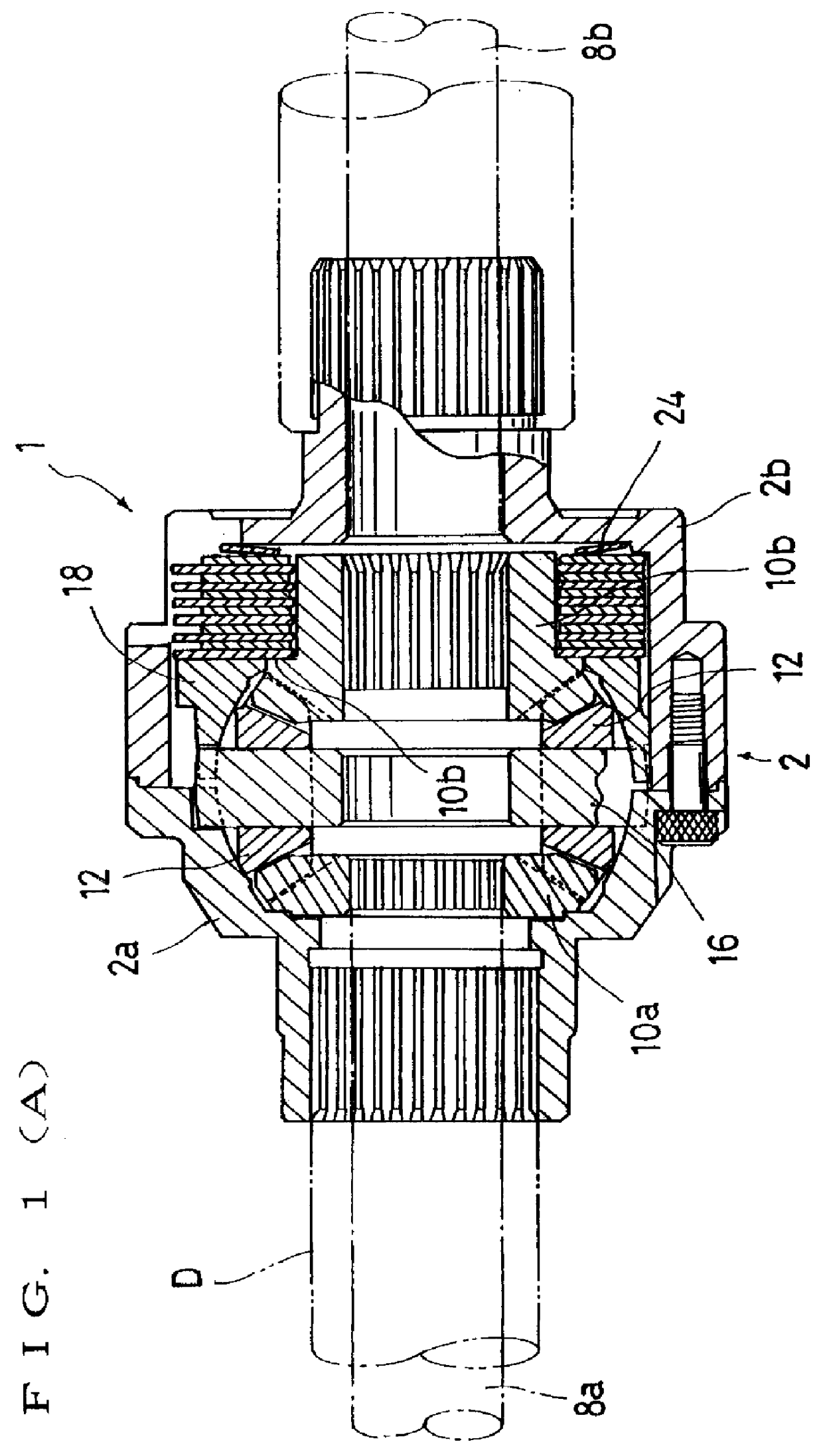
FIGS. 1(A) and 1(B) show a limited slip differential gear (hereinafter referred to as simply LSD) wherein FIG. 1(A) is a sectional view of the LSD and FIG. 1(B) is a view showing a pressure ring as viewed from the outside.

Further, FIG. 4 is a perspective view showing the external appearance of the LSD, FIG. 5 shows halved gear cases, FIG. 6 is a perceptive view of the pressure ring and FIG. 7 is an exploded perspective view of both side gears and pinion gears.

As shown in FIG. 1(A), an LSD 1 has a basic structure in which a first gear case 2a fixed to a driving shaft D by a spline is turned and a second gear case 2b connected with the first gear case 2a is also turned when a driving force of an engine is transmitted to a driving shaft D to turn the driving shaft D.

A gear case 2 comprises the first and second gear cases 2a and 2b as evident fro...


PUM


Abstract

A limited slip differential gear that is simple in construction, small in size and light in weight is provided. The limited slip differential gear includes a pair of divided gear cases that are turned by a driving force of an engine. A pressure ring provided in one of the gear cases is movable in the direction of the wheel axles. Pinion shafts each have an end that is freely engageably supported between the pressure ring and the gear cases. Pinion gears are turnably supported by the pinion shafts. A pair of side gears mesh with the pinion gears positioned therebetween to transmit the driving force to both wheel axles. A multiple disc clutch mechanism provided between one of the gear cases, the side gears and the pressure ring limits differential motion of the side gears when the pressure ring is moved in an axial outward direction.

Description

1. Field of the InventionThe present invention relates to a limited slip differential gear employed by a vehicle, more particularly to a limited slip differential gear that is small in size, simple in construction and light in weight compared with a conventional limited slip differential gear.2. Prior ArtA so-called limited slip differential gear (hereinafter referred as simply LSD) has been conventionally employed by a vehicle so that the vehicle can pull itself out of the mud when one wheel was got stuck in the mud or preventing swerving phenomenon when the vehicle turns.There is known an LSD of this type, for example, as illustrated in FIG. 8 of Japanese Utility Model Registration No. 3001939.FIG. 8 schematically shows a cross section of the LSD. In an LSD 01, a ring gear 04 meshing with a drive pinion 02 is fixed to differential gear cases (simply referred to as gear cases) 06a and 06b.When a driving force of an engine, not shown, is transmitted to the drive pinion 02, the entir...

Claims


Application Information

Patent Timeline
IPC IPC(8): F16H48/20F16H48/00F16H48/22F16H48/38F16H48/40
CPCF16H48/08F16H48/22F16H2048/201F16H2048/085
Inventor SUGIMOTO, KAZUAKI
Owner ROUTE SIX
Why Eureka
Try Eureka