Method and apparatus for near real-time document skew compensation

a near-real-time document and skew compensation technology, applied in the direction of electrical apparatus, instruments, computing, etc., can solve the problems of reducing the amount of data compression, reducing and similar skew of the resultant image, so as to reduce the amount of memory required and reduce the delay

Inactive Publication Date: 2000-05-16
PRIMAX ELECTRONICS LTD
View PDF19 Cites 68 Cited by
  • Summary
  • Abstract
  • Description
  • Claims
  • Application Information

AI Technical Summary

Benefits of technology

It is an object of the present invention to provide skew compensation as a document is scanned, thereby reducing the amount of memory required to store scanning data while skew is compensated and reducing the delay before portions of the deskewed document image can be processed. This is referred to herein as "near real-time" skew compensation.

Problems solved by technology

If a document page is misaligned with respect to the optical sensor, the resultant image is similarly skewed.
Because the contents of a document page are usually aligned with the page itself, a skewed page usually results in a misalignment with the optical sensor.
Misalignment can reduce the amount of data compression achievable by fax machines and can increase the error rate of OCR processes.
As a result, the ease with which such systems may be used is impaired because operators must take care to ensure that the medium is reasonably well aligned with the optical sensor.
Skew compensation in optical systems such as those disclosed in U.S. Pat. Nos. 5,027,227 and 5,093,653 are unsatisfactory because they require operator input to establish the "skew angle" or the amount of image rotation required to compensate for skew.
Other disadvantages of these systems include requiring large amounts of memory to store the image while the skew angle is established and imposing a considerable delay after scanning before skew is compensated.
Furthermore, the skew compensation techniques disclosed in these patents severely distort the image unless the skew angle is small.
This bandwidth or storage capacity is essentially wasted because this portion of the image does not convey useful information about the contents of the document.

Method used


Image

  • Method and apparatus for near real-time document skew compensation
  • Method and apparatus for near real-time document skew compensation
  • Method and apparatus for near real-time document skew compensation

Examples


Embodiment Construction

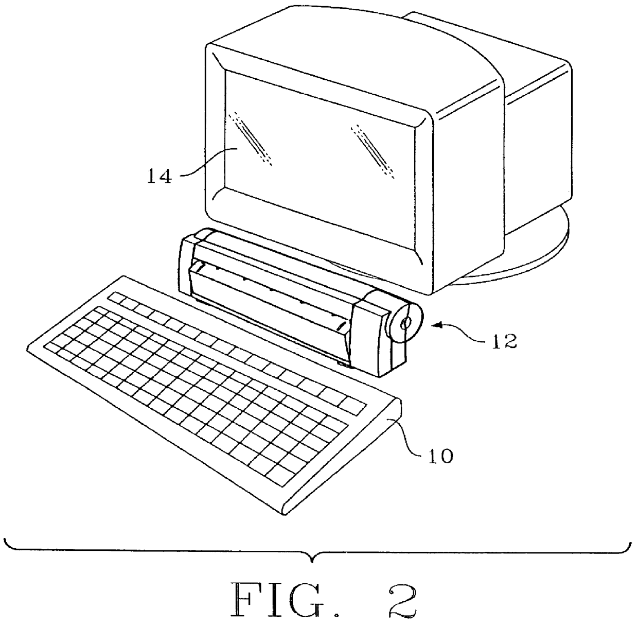
FIG. 5 is a hypothetical graphical representation of a document image as it might be generated by a document imaging system without skew and size / shape detection and skew compensation. The image within frame 100 comprises page image 102, which is skewed with respect to the frame, and area 104 outside the edges of the page image. Document imaging systems incorporating various aspects of the present invention directed toward skew detection and compensation attempt to generate an image in which page image 102 is oriented with respect to frame 100. Document imaging systems incorporating various aspects of the present invention directed toward size / shape detection attempt to generate an image in which frame 100 is substantially coincident with the edges of page image 102.

Basic Structure

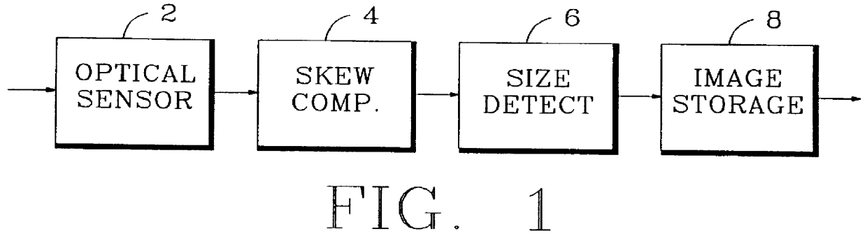
The basic structure of one embodiment of a document imaging system incorporating various aspects of the present invention is illustrated in FIG. 1. Optical sensor 2 generates scanning signals representing ...


PUM


Abstract

A document imaging system detects skew and/or size of a document. In one embodiment, a document imaging system generates scanning signals representing the documents, analyxes the scanning signals to detect one more edges of the document before the entire lenght of the document is scanned, establishes a skew angle between the detected edges and a reference orientation, and modifies the scanning signals to compensate for skew while the document is being scanned. In another embodiment, a document imaging system detects one or more edges of a document, defines a polygon having sides substantially congruent with the detected edges, and establishes the size of the document in response to the polygon.

Description

The present invention relates in general to optical scanning and image processing, and relates more particularly to a document imaging system which detects skew and / or size / shape of a document image, and for compensation of skew.Document imaging technology is used in a growing number of business and other applications such as facsimile or "fax" machine transmissions, optical character recognition (OCR), the digitizing of photographs and artwork, and photocopy machines. In many of these applications, best results are usually obtained if document contents are properly aligned with an optical sensor used to generate an image of the document and if the size and / or shape of the document can be established.If a document page is misaligned with respect to the optical sensor, the resultant image is similarly skewed. Because the contents of a document page are usually aligned with the page itself, a skewed page usually results in a misalignment with the optical sensor. Misalignment can reduc...

Claims


Application Information

Patent Timeline
Patent Type & Authority Patents(United States)
IPC IPC(8): G06K9/32H04N1/387H04N1/00G06V30/10
CPCG06K9/3283H04N1/00681H04N1/00708H04N1/00718H04N1/3878H04N1/00734H04N1/00745H04N1/00753H04N1/00766H04N1/00721G06V30/1478G06V30/10
Inventor PASCO, RICHARD CLARKPAPUC, SORIN VASILECOTTE, PIERRE-ALAIN
Owner PRIMAX ELECTRONICS LTD
Why Eureka
Try Eureka