Device for avoiding cavitation in injection pumps

a technology of cavitation and injection pump, which is applied in the direction of liquid fuel feeders, fuel injection with fuel accumulators, engine components, etc., can solve the problems of insufficient orifice erosion, insufficient orifice maintenance pressure, and inability to maintain high and sufficient pressure, so as to reduce the wear of components, reduce the frequency, and minimize the dispersion of metal particles

Inactive Publication Date: 2000-05-23
SEMT PIELSTICK
View PDF8 Cites 26 Cited by
  • Summary
  • Abstract
  • Description
  • Claims
  • Application Information

AI Technical Summary

Benefits of technology

The advantages of the device lie in reduced wear of the components of the injection pump, thus making it possible to perform maintenance at reduced frequency and minimizing the dispersion of metal particles in the fuel.

Problems solved by technology

At the interface between the jet of expelled fuel and the fuel at low pressure, this gives rise to the appearance of bubbles due to degassing which, combined with the travel speed, give rise to erosion of the walls of the return orifices by cavitation, which erosion can lead to destruction of the injection pump.
The drawback of that device is that the permanent link does not enable high and sufficient pressure to be maintained in the orifices before emptying takes place.
This pressure arises only when the emptying flow appears, and that is not sufficient for avoiding orifice erosion effectively.

Method used


Image

  • Device for avoiding cavitation in injection pumps
  • Device for avoiding cavitation in injection pumps
  • Device for avoiding cavitation in injection pumps

Examples


Embodiment Construction

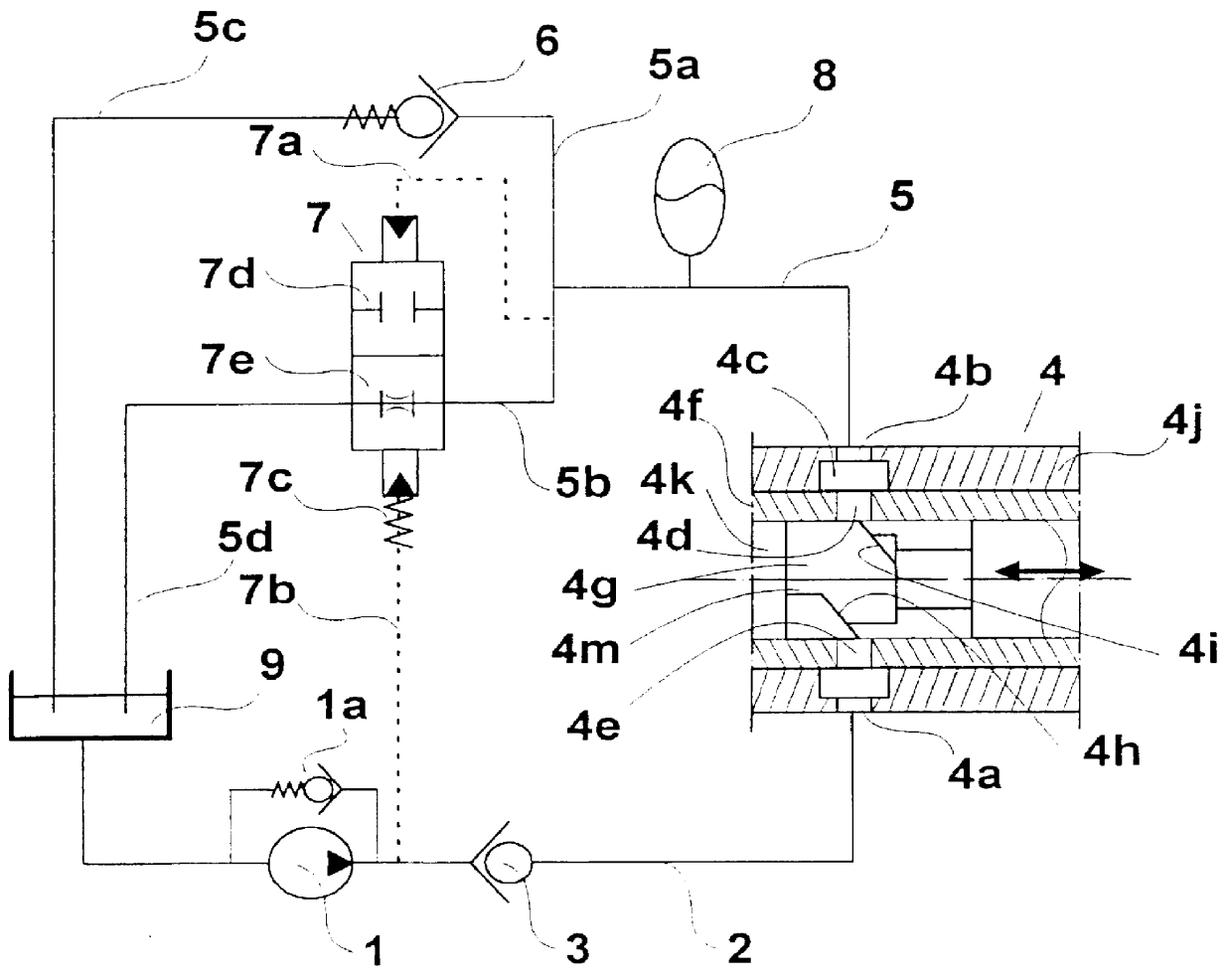
In FIG. 1, a duct 2 provided with a check valve 3 connects a fuel circulation pump 1 fed from a tank 9 to a fuel injection pump 4 shown in part only, being represented by its feed orifice 4a. The delivery pressure of the pump 1 is limited by a rated check valve 1a. The main return duct 5 and the secondary ducts 5a and 5b connect the return orifice 4b of the injection pump 4 in parallel to a rated check valve 6 and to a two-port valve 7. The two-part valve 7 is pilot controlled via a line 7a by the pressure which obtains in the duct 5b, and via a line 7b by the pressure which obtains in the duct 2 upstream from the rated check valve 3. A spring 7c reinforces the pilot control action due to the pressure in the line 7b, and holds the valve 7 in the open position in the absence of a large pressure difference between the two pilot lines. In the position 7e, the valve 7 puts into operation a restriction that gives rise to headloss for maintaining a certain level of fuel pressure upstream ...


PUM


Abstract

The invention provides a device for eliminating cavitation in the excess fuel return orifice(s) in the compression chamber of a fuel injection pump of an internal combustion engine after the end of the injection stage, said injection pump being connected firstly to a feed duct including a first check valve having low headloss enabling fuel to reach the compression chamber, and secondly to an excess fuel return duct, wherein the return duct comprises in parallel and close to the return orifice of the injection pump, a second check valve that is rated to cause the pressure in said return orifice of the injection pump to rise, and a two-port valve that is normally open and that is caused to close by the appearance of pressure in the return orifice greater than the pressure which obtains in the feed duct upstream from said first check valve.

Description

The present invention relates to a device designed to eliminate cavitation in the excess fuel return orifice(s) in the compression chamber of a fuel injection pump of an internal combustion engine after the end of the injection stage.This stage in the operation of an injection pump, referred to as "emptying", causes excess fuel to be expelled at very high pressure and at very high speed through return orifices where the fuel that is already present is at low pressure. At the interface between the jet of expelled fuel and the fuel at low pressure, this gives rise to the appearance of bubbles due to degassing which, combined with the travel speed, give rise to erosion of the walls of the return orifices by cavitation, which erosion can lead to destruction of the injection pump. One of the means for eliminating this cavitation is to increase the pressure which obtains in the return orifices of an injection pump when emptying takes place. Devices are known such as that described in docu...

Claims


Application Information

Patent Timeline
Patent Type & Authority Patents(United States)
IPC IPC(8): F02M59/00F02M55/00F02M59/46F02M63/00F02M55/02F02M59/44
CPCF02M55/001F02M2200/40F02M2200/04F02M59/44
Inventor ZYCH, EDMOND
Owner SEMT PIELSTICK
Why Eureka
Try Eureka