One-touch lock valve and raw material container

a technology of one-touch lock valve and raw material container, which is applied in the direction of valve details, valve arrangement, preventing unauthorised/accidental actuation, etc., can solve the problems of process fluid leaked, toxicity and flammability, and often has very hazardous properties of process fluid, etc., to prevent wear and tear, excellent operability, and easy operation

Active Publication Date: 2020-06-04
KITZ SCT
View PDF0 Cites 3 Cited by
  • Summary
  • Abstract
  • Description
  • Claims
  • Application Information

AI Technical Summary

Benefits of technology

[0024]From the invention according to claim 1, the lock mechanism is arranged in the holder and the rotating handle, and this lock mechanism is formed of the spring inserted into the holder, the spherical body provided on the lower spring-back side of the spring, the lock member while having the midway on the rear end side axially attached to the holder and having the rear end part pressed by spring-back via the spherical body, having the tip part side abutting on the rotating handle, and the engagement groove where the tip end part side of this lock member is locked and, in a state in which the lock member is at a position opposed to the engagement groove, an automatic lock is made in a state in which this lock member is pressed by spring-back into the engagement groove, thereby reliably prevent opening / closing operation of the rotating handle when not necessary such as those by inadvertent external forces or nonintentional operation. In this case, compactness as a whole is maintained by the simple inner mechanism having the lock member and the engagement groove without externally and separately providing a component for locking, and the valve can be used also in a narrow place. At the time of operation, as the lock member is removed from the engagement groove, the rotating handle is rotated, thereby allowing unlocking with one touch by a light force. After unlocking, in a state in which the lock member is removed from the engagement groove, the rotating handle can be rotated while the lower edge part of the rotating handle is in contact with the lock member, thereby allowing operation by a light operation force to any opening / closing or intermediate degree of opening. At the time of unlocking or during rotating operation, a large load is not applied to each component, and thus each component is prevented from wearing out and excellent operability is maintained.
[0025]From the invention according to claim 2, the spherical body is pressed by spring-back via the spring receiver attached below the spring, the lock member is pressed by spring-back toward the lower edge part of the rotating handle in the state in which the hemispherical part formed at the rear end part of the lock member is engaged via the spherical body, and the tip of the lock member is caused to protrude to some extent from the sideward direction of the rotating handle. Thus, the force of the spring can be transmitted from the lock member to a rotating handle side by using leverage. With this, at the time of unlocking, the lock member can be operated with ease by a small force and at a small rotation angle. At the time of operation of the rotating handle, an influence of the spring-back force of the spring on the operation of the rotating handle is reduced to allow rotating operation by a small force, and the rotating handle rotates so as to slide over the outer peripheral surface of the lock member, thereby decreasing sliding resistance to reduce wear of the components. Furthermore, the lock member protruding to some extent from the sideward direction of the rotating handle can be operated with ease by a finger.
[0026]From the invention according to claim 3, at the valve-close position of the rotating handle, this full-close state can be automatically locked. Furthermore, even when each product has an error in process accuracy of internal components or an internal component is loosened due to repetitive rotating operation or the like to change the valve-close position of the rotating handle, the relation between the lock member and the engagement groove can be finely adjusted in accordance with the rotating state of the rotating handle in the valve-close state, and an automatic lock can be reliably made at the valve-close position of the rotating handle.
[0027]From the invention according to claim 4, the display part for full-open and full-close can be visually recognized from the visual recognition window, and valve-closing operation can be performed while a state of becoming automatically locked is checked from this display part. Also, by finely adjusting the degree of valve-opening while visually recognizing the display part, adjustment can be made to a desired degree of valve-opening.
[0028]From the invention according to claim 5, the check rod moves up and down by operation of the lock member and, by visually recognizing the exposed state of the upper end of this check rod via the through hole of the display part of the holder, the operation state of the lock member can be checked from above the valve main body.
[0029]From the invention according to claim 6, since the unlocked state or the locked state of the rotating handle can be visually recognized from outside from the exposed state of the upper end of the check rod from the display part, erroneous operation of the lock member and a lock-incomplete state can be reliably prevented.

Problems solved by technology

This process fluid often has very hazardous properties such as toxicity and flammability.
In this case, it is dangerous if the handle is loosened by an inadvertent external force such as vibration, impact, and others at the time of delivery of the raw material container or the like.
Moreover, if the handle is rotated by an unintentional operation such as erroneous operation after the raw material container is connected to a raw material supply line or the like, the process fluid may be leaked, possibly leading to a disaster.

Method used


Image

  • One-touch lock valve and raw material container
  • One-touch lock valve and raw material container
  • One-touch lock valve and raw material container

Examples


Embodiment Construction

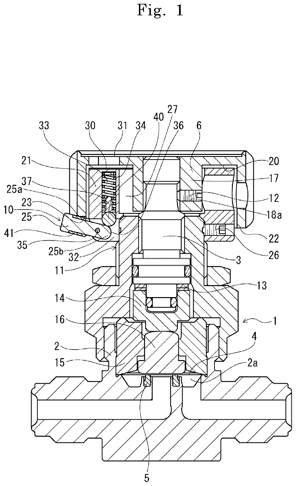
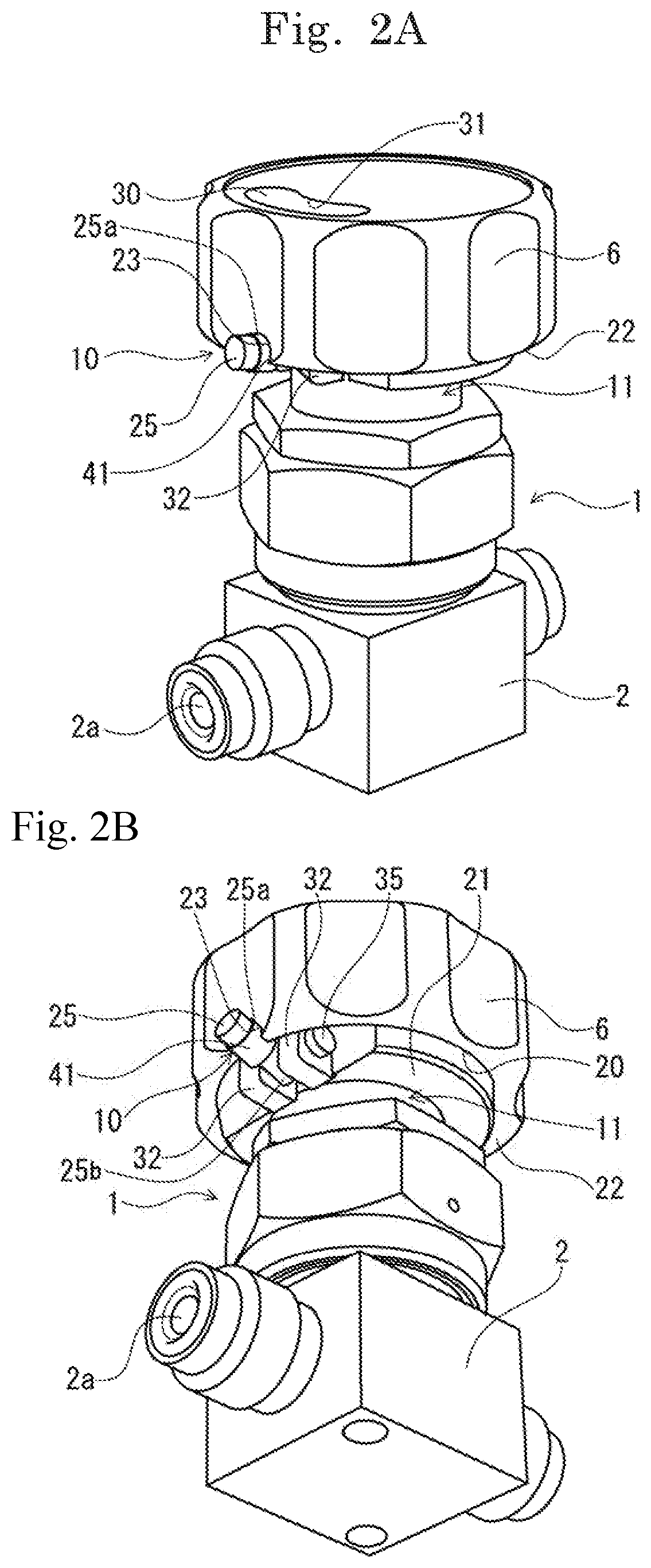
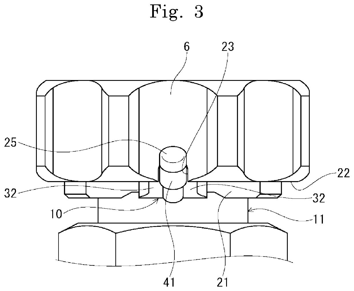
[0043]In the following, embodiments of the one-touch lock valve and the raw material container in the present invention are described in detail based on the drawings. In FIG. 1 and FIG. 3, depicted is a valve-close state of an embodiment of the one-touch lock valve of the present invention. In FIG. 4 and FIG. 5, depicted is a state in which the one-touch lock valve is unlocked.

[0044]In the drawings, a one-touch lock valve (hereinafter referred to as a valve main body 1) has a body 2, a stem 3, a diaphragm 4 as a valve body, a valve seat 5 for sealing, a rotating handle 6, a lock mechanism 10, and a holder 21.

[0045]The valve main body 1 is formed of a diaphragm valve. Inside the body 2 of this valve main body 1, the diaphragm 4 is incorporated. This body 2 is provided with a axial mounting part 11 with the stem 3 axially mounted in a screwed state.

[0046]To an upper part of the stem 3, the rotating handle 6 is integrally attached by spline coupling, and the rotating handle 6 is fasten...


PUM


Abstract

A one-touch valve including a valve main body (1) having a valve body incorporated therein, a stem (3) mounted on the valve main body, a rotating handle (6) fixedly attached to an upper part of the stem, a holder (21) accommodated in the rotating handle, and a lock mechanism (10) arranged in the holder and the rotating handle. The lock mechanism is formed of a spring inserted into the holder, a spherical body provided on a lower spring-back side of the spring, a lock member having a midway on a rear end side axially attached to the holder, having a rear end part pressed by spring-back via the spherical body, and having a tip part side abutting on a lower edge part of the rotating handle in a spring-back state, and an engagement groove where the tip end part side of the lock member is locked by the rotating handle.

Description

TECHNICAL FIELD[0001]The present invention relates to one-touch lock valves and raw material containers capable of opening and closing, for example, a flow path of a process fluid for use in semiconductor manufacturing, for locking with one touch.BACKGROUND ART[0002]Conventionally, as a process fluid for use in semiconductor manufacture, a material for gasification made of a liquid or solid is used. This process fluid often has very hazardous properties such as toxicity and flammability. Thus, a raw material container for delivering and storing that raw material is required to be strictly sealed so as not to leak the raw material to the outside. On the other hand, to let the process fluid flow from the inside of the raw material container to the outside, it is also required to make the inside communicate with an outer flow path. From this, normally, a valve is provided to an upper surface side of the raw material container, and this valve is generally provided with a manual handle f...

Claims


Application Information

Patent Timeline
Patent Type & Authority Applications(United States)
IPC IPC(8): F16K35/02F16K31/60
CPCF16K35/025F16K31/60F16K1/305F16K31/607F16K35/02F16K37/0058
Inventor KOGURE, YUSAKU
Owner KITZ SCT
Why Eureka
Try Eureka