Punch and die for producing connector plates

a technology of punching die and connector plate, which is applied in the direction of forging/pressing/hammering apparatus, shaping tools, applications, etc., can solve the problems of connector plate teeth being stripped from the die block, fracturing the root of the connector plate, and affecting the production of connector plate teeth

Inactive Publication Date: 2000-05-23
ILLINOIS TOOL WORKS INC
View PDF52 Cites 53 Cited by
  • Summary
  • Abstract
  • Description
  • Claims
  • Application Information

AI Technical Summary

Benefits of technology

Numeral references are employed to designate like parts throughout the various figures of the drawing. Terms such as "left," "right," "clockwise," "counter-clockwise," "horizontal," "vertical," "up" and "down" when used in reference to the drawings, generally refer to orientation of the parts in the illustrated embodiment and not necessarily during use. The terms used herein are meant only to refer to relative positions and / or orientations, for convenience, and are not to be understood to be in any manner otherwise limiting. Further, dimensions specified herein are intended to provide examples and should not be considered limiting.

Problems solved by technology

Problems are often encountered in the production of connector plate teeth.
One such problem occurs as a formed connector plate is stripped from the die block.
Another such problem is the fracturing of connector plate teeth at their roots as they are bent over the ends of the die cavity.
Further, some currently used punch and die sets produce unwanted "viper teeth," or teeth with tears or rips along the side edges.
This is especially a problem when higher grade steels are used to produce the connector plates.
Unwanted fractures and tears reduce the strength of connector plate teeth and detrimentally affect the performance of the plate.

Method used


Image

  • Punch and die for producing connector plates
  • Punch and die for producing connector plates
  • Punch and die for producing connector plates

Examples


Embodiment Construction

Connector plates are produced by feeding a steel plate into a stamping press. In the press, the steel plate is stamped between a plurality of punches, such as the one seen in FIG. 1, and a corresponding receiver or die block, as seen in FIG. 8. The formed connector plate, such as the one seen connecting two truss members in FIG. 13, is comprised of a planar steel backing having a plurality of elongated slots. Each slot has a tooth at each end extending generally perpendicular to the backing, as seen in FIG. 12.

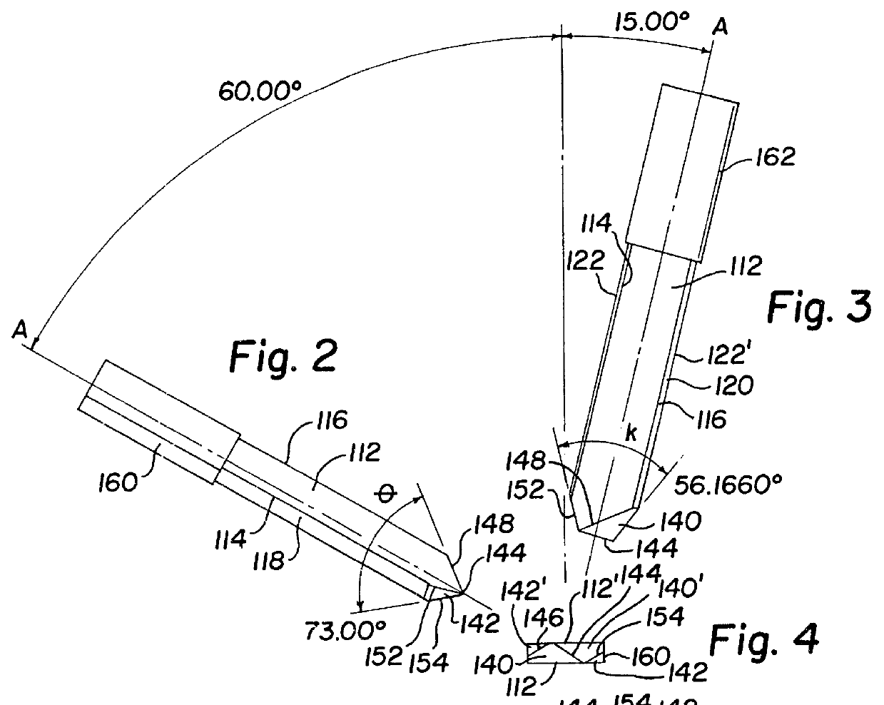
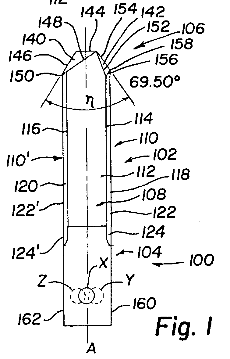
A blade or lance punch 100, as seen in FIG. 1, consists of an elongated blade 102 extending from a shank 104 to a metal working tip 106. FIG. 1 shows the front view of punch 100; it is understood that the hidden back view of the punch has corresponding symmetry. The elongated blade 102 is defined by opposing punch sides 108 and 108' and opposing punch ends 110 and 110'. The opposing punch sides 108 and 108' comprise parallel spaced planar punch side walls 112 and 112' each hav...


PUM

PropertyMeasurementUnit
forming angleaaaaaaaaaa
angleaaaaaaaaaa

Abstract

A blade punch for forming teeth in a connector plate, the blade punch comprising an elongated blade having a metal working tip at one end and a shank at the other end. The blade has an elongated cross-section defined by opposing parallel spaced planar side walls and opposing ends. Each end comprises a major end wall and a minor end wall which converge to end wall intersections, where the end wall intersections are eccentric to a plane parallel to and midway between said side walls. Each end wall intersects a side wall at an obtuse angle. The metal working tip has opposed air cut faces abutting one another along an air cut edge and opposed first and second forming faces, each of the forming faces abutting one of the air cut faces along an exterior edge. Each of the air cut faces is bordered by a portion of one of the minor end walls, a portion of one of the side walls, the air cut edge, and one of the exterior edges. Each of the forming faces is bordered by a portion of one of the major end walls, a portion of one of the minor end walls, a portion of one of the side walls, and one of the exterior edges. A forming angle between 50 DEG and 60 DEG is formed between the first forming face and the exterior edge bordering the second forming face in a plane normal to the first forming face.

Description

This invention relates to a lance punch tool and a cooperating die or receiver used for producing teeth in truss connector plates.BACKGROUND OF INVENTIONConnector plates are typically used to connect wood members to form trusses and joists. Connector plates are produced by feeding a steel plate into a stamping press. In the press, the steel plate is punched between a plurality of blade punches and a corresponding number of die cavities in a receiver or die block. In use, a connector plate has a planar steel backing with a plurality of teeth extending generally perpendicular to the backing.Manufacturers of connector plates are constantly seeking ways to increase the strength characteristics of the connector plate teeth and to improve the methods of manufacture. The shape and strength characteristics of the teeth depend largely on the configuration of the blade punch and the die used to produce the teeth.Problems are often encountered in the production of connector plate teeth. One su...

Claims


Application Information

Patent Timeline
Patent Type & Authority Patents(United States)
IPC IPC(8): B21D31/00B21D31/02F16B15/00E04B1/38B21D28/14
CPCB21D31/02F16B15/0046Y10S52/06Y10S403/11Y10S403/12Y10S403/15Y10S411/921
Inventor LEES, WILLIAM F.
Owner ILLINOIS TOOL WORKS INC
Why Eureka
Try Eureka