Individually accessible macrocell

a macrocell, individual technology, applied in the direction of pulse technique, computation using denominational number representation, instruments, etc., can solve the problems of continuous cycling adding to consume power, and it is difficult to implement the remaining logic functions which the pld array must perform

Inactive Publication Date: 2000-05-23
STMICROELECTRONICS SRL
View PDF6 Cites 75 Cited by
  • Summary
  • Abstract
  • Description
  • Claims
  • Application Information

AI Technical Summary

Benefits of technology

It is an object of the present invention to provide an improved PLD circuit.

Problems solved by technology

This continual cycling adds to consumes power.
Still further, routing the address and data bus data through the macrocells utilizes the critical PRESET, CLEAR, CLOCK and OR product terms, making it hard to implement the remaining logic functions which the PLD array must perform, not to mention the time required to develop the logic functions which respond to the address and data bus signals.

Method used


Image

  • Individually accessible macrocell
  • Individually accessible macrocell
  • Individually accessible macrocell

Examples


Embodiment Construction

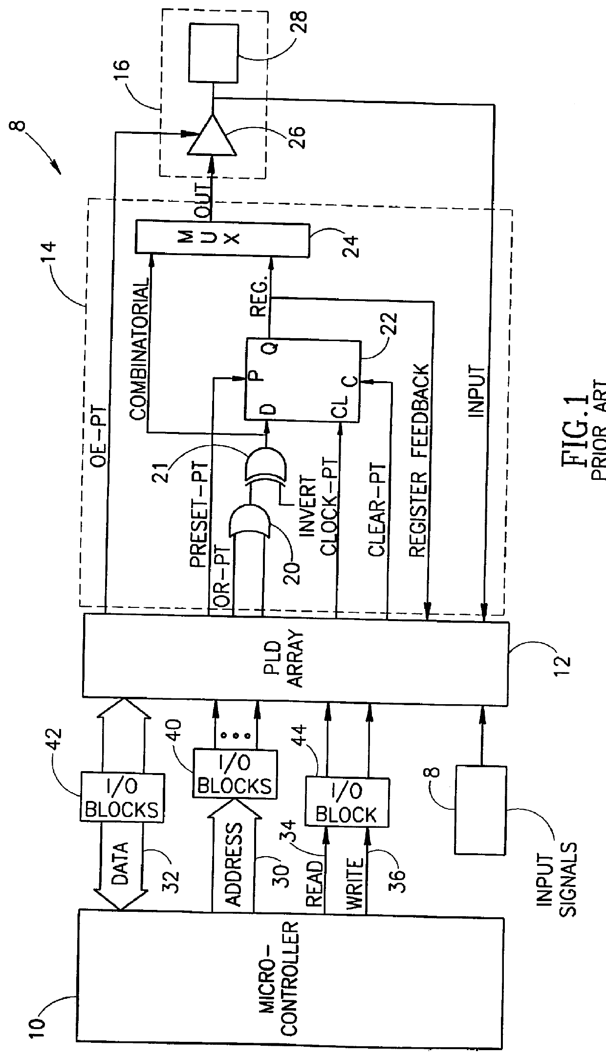
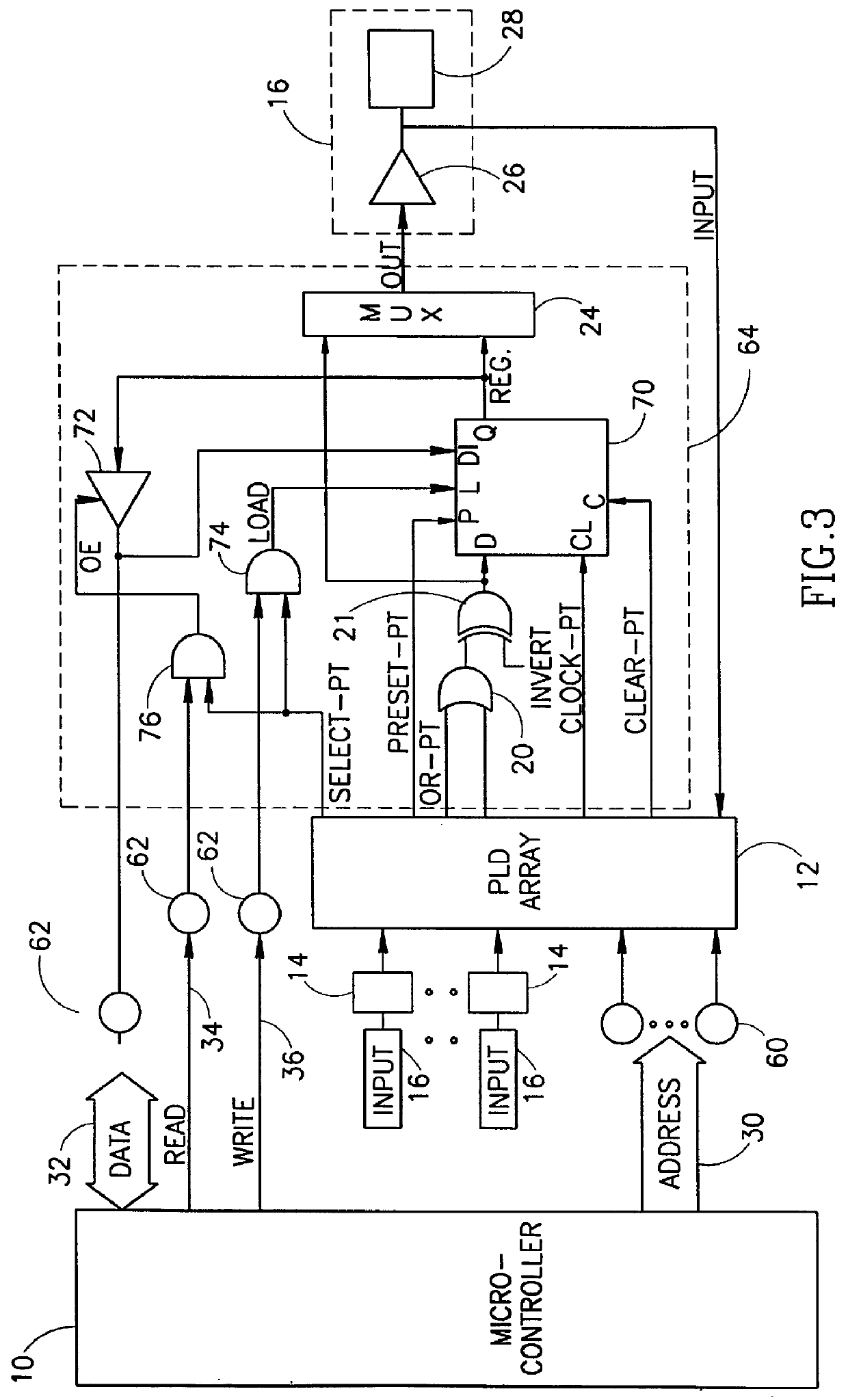
Reference is now made to FIG. 3 which illustrates a programmable logic device (PLD) and macrocell array providing direct access between the macrocell and the data bus and between the address bus and the PLD array for the purpose of reading from and writing to specific macrocells. Elements of FIG. 3 which are similar to those of FIG. 1 carry similar reference numerals.

As in the prior art, PLD array 12 communicates with the external world indirectly (i.e. through macrocells 14 and input / output units 16). In addition, in accordance with a preferred embodiment of the present invention, the address bus 30 is directly connected to PLD array 12 (rather than through a macrocell) and the data bus 32 directly communicates with the macrocell storing data of interest. This significantly reduces the number of macrocells which are dedicated for interaction with the address and data busses.

Specifically, address bus 30 is connected directly to N pins 60 (shown as a single block for clarity), where ...


PUM


Abstract

A circuit connectable to a microcontroller having an address bus, a data bus, a read line and a write line include a programmable logic device (PLD) array, at least one input pin, at least two databus macrocells and a bit mask register. The input pin is connected to the PLD array and is connectable to the address bus. The databus macrocell is connected to the PLD array and to an external unit and is also connectable to the data bus, the read line and the write line. The bit mask register has at least two bits, each associated with one of the at least two macrocells. The databus can directly access the databus macrocell only if its associated bit in the bit mask register is of the correct state. In another embodiment, the write line carries an edge write signal and the databus accesses the databus macrocell on one edge of the edge write signal.

Description

The present invention relates to programmable logic devices, their macrocells and their connections to a microcontroller interface bus.Programmable logic devices (PLDs) perform logic functions quickly on a multiplicity of input signals. As shown in FIG. 1 to which reference is now made, an array of PLDs, labeled 12, receives input signals via input / output blocks 8. The results of the logic functions are known as "product terms" and are output from the PLD array 12 to one or more blocks 8, each of which comprises a macrocell 14 and an input / output unit 16.Each macrocell 14 comprises an OR gate 20, a XOR gate 21, a flip-flop 22 and a multiplexer 24. The OR gate 20 performs OR operations on at least two "OR-PT" type product terms and the XOR gate 21 selectively passes or inverts the output of OR gate 20. The result is provided to the data (D) input of the flip-flop 22. Other product term signals, such as the CLOCK-PT, PRESET-PT and CLEAR-PT product terms, control the operation of flip-...

Claims


Application Information

Patent Timeline
Patent Type & Authority Patents(United States)
IPC IPC(8): G06F15/76G06F15/78H03K19/177G06F13/38H03K19/173
CPCG06F15/7867H03K19/17744H03K19/17704
Inventor LEE, CHINGCEDAR, YORAM
Owner STMICROELECTRONICS SRL
Why Eureka
Try Eureka