Non vibration tread angle for rubber track

a tread angle and rubber track technology, applied in endless track vehicles, wheel attachments, transportation and packaging, etc., can solve the problems of tread-wheel vibration on both rough surfaces and relatively smooth surfaces, significant vibration in the vehicle and a generally rough ride, and vibration of the tread-wheel

Inactive Publication Date: 2000-05-30
BRIDGESTONE CORP +1
View PDF15 Cites 39 Cited by
  • Summary
  • Abstract
  • Description
  • Claims
  • Application Information

AI Technical Summary

Problems solved by technology

Tracked vehicles are typically designed to be operated on rough surfaces, that produce significant vibrations in the vehicle and a generally rough ride.
Although surface-related vibrations are expected on rough surfaces, tread-wheel vibration occurs on both rough surfaces and on relatively smooth surfaces.
Tread-wheel vibration is caused by the wheels of the vehicle experiencing alternating stiffnesses while traveling over the endless track.
The stiffnesses create vibrations in the wheels and thus the vehicle.
Such a design would not, however, provide sufficient traction.
Tread-wheel vibration is detrimental to the longevity of the wheel bearings, axles, etc. and increases the frequency of maintenance required on the tracked vehicle.
Tread-wheel vibration also decreases the comfort of the vehicle's ride.

Method used


Image

  • Non vibration tread angle for rubber track
  • Non vibration tread angle for rubber track
  • Non vibration tread angle for rubber track

Examples


Embodiment Construction

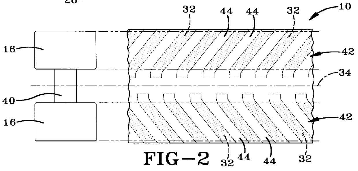
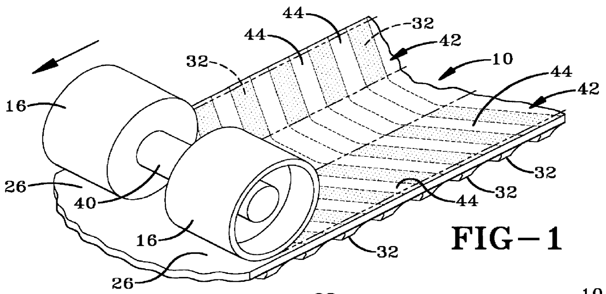
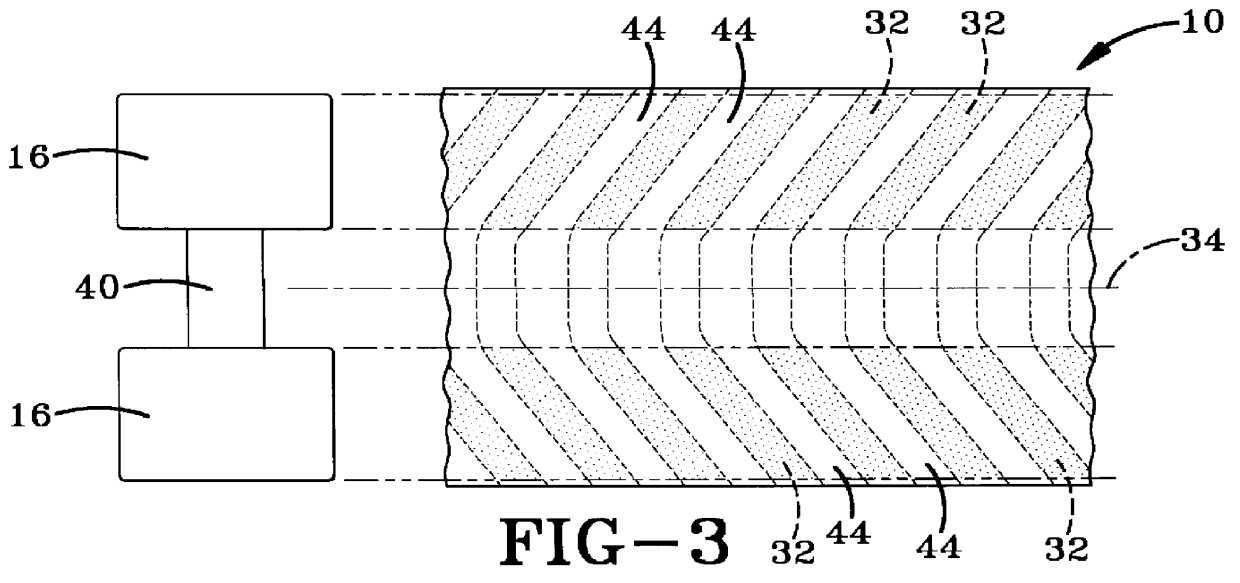
The endless track made in accordance with the present invention is indicated generally by the numeral 10 in the accompanying drawings. Track 10 is depicted schematically in FIG. 8 as being disposed about a plurality of drive wheels that may be used to drive a typical off-highway vehicle. The drive wheels may contain a powered drive wheel 12, a plurality of idlerwheels 14, and a plurality of bogey wheels 16. As it may be seen in FIG. 11, track 10 includes a main body 20 that carries a plurality of reinforcing plies that may be calendared plies of metallic wires or cables 22. Track 10 also includes a series of inner lugs 24 that are configured to engage drive wheel 12 so that drive wheel 12 may drive track 10 about wheels 12, 14, and 16. Inner lugs 24 are centrally disposed and longitudinally aligned. Substantially planar, endless longitudinal areas are disposed on either side of inner lugs and are indicated by the numeral 26. The track tread 28 is disposed on the exterior of track 10...


PUM


Abstract

A track (10) for a vehicle is typically carried by a plurality of wheels (12, 14, 16). Tread-wheel vibration is created when the track (10) passes between a wheel and the ground over which the vehicle is traveling. A track (10) includes a plurality of external lugs (32) that engage the ground when the track (10) is in use. Each external lug (32) has a tread angle (a) indicating the angle at which the lug is disposed to the longitudinal axis (34) of the track (10), a tread pitch (P) and a lug width (H). A wheel (16) contacting the interior of the track (10) has a width (B). A tread design that minimizes tread-wheel vibration has the pitch (P) of the lugs (32) substantially equal to the wheel width (B) multiplied by the tangent of the tread angle (a).

Description

1. Field of InventionThe present invention relates generally to endless tracks for off-highway vehicles and, more particularly, to a track configuration that minimizes treadwheel vibration. Specifically, the present invention relates to the relationship between the tread angle and wheel width in an endless track that minimize tread-wheel vibration in the wheels about which the track is disposed.2. Background of the InventionAn endless track is often fabricated from an elastomeric material reinforced with calendared plies of steel belts or the like. The outside surface of the endless track typically is provided with a plurality of spaced lugs that are designed to grip rough, broken, or soft ground and provide traction to the vehicle employing the track. The inner surface of the track typically has a pair of relatively smooth runners spaced from each other by a centrally-disposed lug section that is engaged by a drive wheel to drive a track about the supporting drive wheel assembly. T...

Claims


Application Information

Patent Timeline
Patent Type & Authority Patents(United States)
IPC IPC(8): B62D55/24B62D55/253
CPCB62D55/24B60C2011/0313B62D55/00
Inventor AKIYAMA, HITOSHIBEATTY, MATTHEW J.AGOCS, JR., LOUIS F.
Owner BRIDGESTONE CORP
Why Eureka
Try Eureka