Fabricating a floating gate with field enhancement feature self-aligned to a groove

Inactive Publication Date: 2000-05-30
GLOBALFOUNDRIES INC
View PDF4 Cites 26 Cited by
  • Summary
  • Abstract
  • Description
  • Claims
  • Application Information

AI Technical Summary

Benefits of technology

An objective of the present invention is to provide a fabrication technique for producing pointy floating gate structures that are also smaller than the lithographically defined image, thereby permitting use of older photolithographic technology o

Problems solved by technology

The LOCOS process results in birds beak creating the sharp points, but also re

Method used


Image

  • Fabricating a floating gate with field enhancement feature self-aligned to a groove
  • Fabricating a floating gate with field enhancement feature self-aligned to a groove
  • Fabricating a floating gate with field enhancement feature self-aligned to a groove

Examples


Embodiment Construction

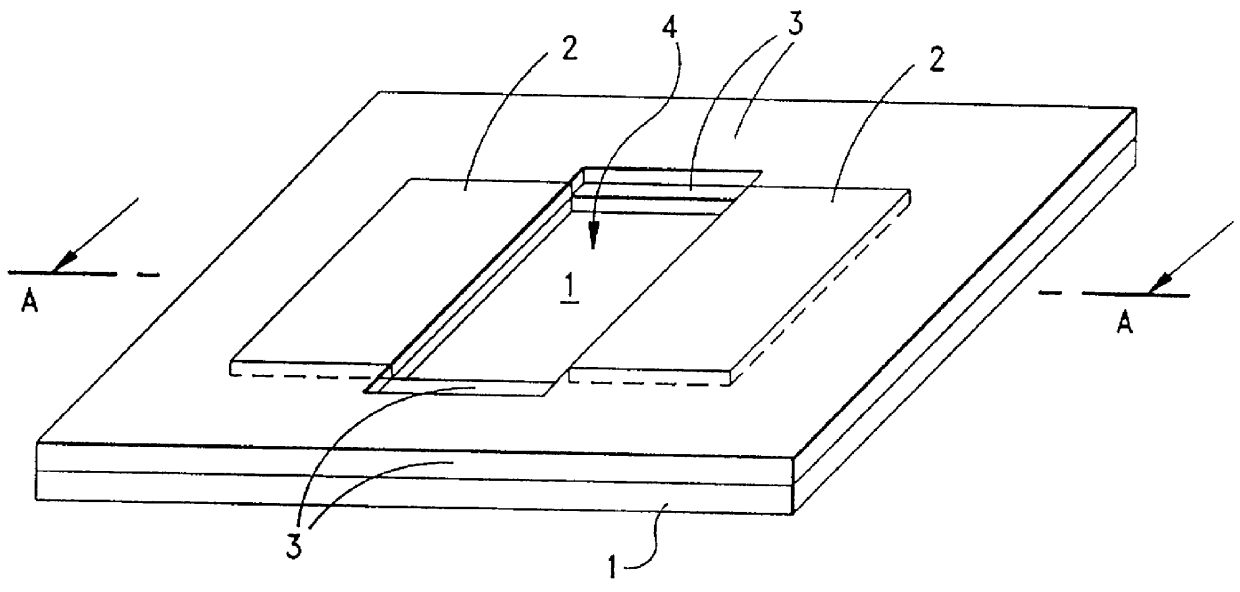
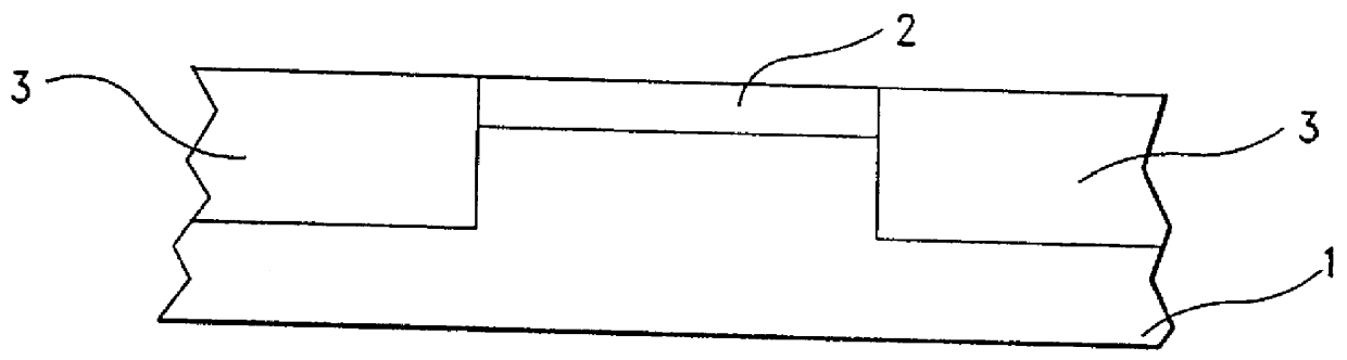
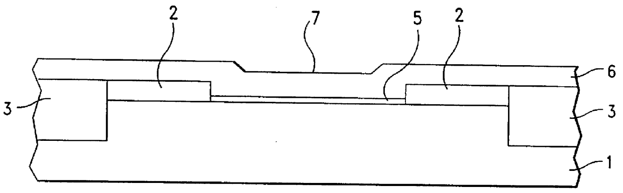
In order to facilitate an understanding of the present invention, reference will be made to the figures which illustrate diagrammatic representations of the steps of various embodiments of the present invention. According to one aspect of the present invention, a first insulating layer 2 is formed on a semiconductor substrate 1. The semiconductor substrate 1 is typically silicon but can be any other semiconductor material such as group III-IV semiconductor. The insulating layer 2 can be grown on the substrate or can be provided by deposition techniques such as chemical vapor deposition (CVD). Insulating layer 2 is typically silicon nitride and conventionally referred to as the pad nitride. Typically, this layer is about 200 to about 5000 .ANG. thick and more typically about 1000 to about 2500 .ANG. thick. Predetermined portions of the first insulating layer 2 are removed as well as removing some of the substrate 1 located beneath the removed portions of this first insulating layer. ...


PUM


Abstract

Floating gates with field enhancement features are produced by a technique that makes possible structures smaller than the lithographically defined image. The floating gates produced having sharp tips for source-side injection flash memory cells. Moreover, the process provides an insulator cap over the floating gate that is self-aligned.

Description

DESCRIPTION1. Technical FieldThe present invention is concerned with a process for providing a field enhancement floating gate. In particular, the present invention is concerned with fabricating a floating gate having sharp tips especially for a source-side injection flash memory cell. More particularly, the process of the present invention provides floating gates having sharp points along with an insulation cap that is self-aligned to a pre-existing topography. The present invention makes it possible to create sublithographic devices along with a floating gate having enhanced or sharper edges. In addition, the present invention is concerned with devices obtained by the above process.2. Background of InventionField effect transistors (FETs) employing a so-called "floating gate" along with a control gate are well known. The floating gate differs from a control gate in that it has no direct electrical connection to any external component and is surrounded by isolation on all sides. Th...

Claims


Application Information

Patent Timeline
IPC IPC(8): H01L21/02H01L21/336H01L29/40H01L29/423
CPCH01L29/66825H01L29/42324
Inventor MILES, GLEN L.LEIDY, ROBERT K.
Owner GLOBALFOUNDRIES INC
Why Eureka
Try Eureka