Dome switch assembly system

a technology of assembly system and dome switch, which is applied in the direction of moving contacts, emergency contacts, electrical equipment, etc., can solve the problems of increased manufacturing costs due to manual labor and increased cost of manually repositioning the dome switch

Inactive Publication Date: 2000-06-13
ODORFER RICHARD A
View PDF11 Cites 19 Cited by
  • Summary
  • Abstract
  • Description
  • Claims
  • Application Information

AI Technical Summary

Benefits of technology

Even further, in accordance with a preferred embodiment thereof, the present invention provides a machine method for providing, for dome switches of the type wherein each dome switch comprises an approximately hemispherical top surface having an apex, a complete dome switch assembly having a circuit layer, a retaining cover layer, a spacer layer having a plurality of openings for respectively receiving a plurality of dome switches, a release liner, and an overlay layer, comprising the steps of: positioning on a machine table having a machine-movable surface an initial assembly comprising such circuit layer, circuit side upwards, and adjacent such circuit side of such circuit layer, such spacer layer, having a spacer layer top surface; situating such dome switches, affixed in a dome switch reel, over such machine-movable surface of such machine table; machine-blanking respective such dome switches into respective such openings of such spacer layer; placing such retaining cover layer, having a retaining cover top surface, on such spacer layer top surface; and placing such overlay layer, having an icon side, with such icon side upwards, on such retaining cover top surface; thereby making a complete dome switch assembly.

Problems solved by technology

Typically, each dome switch assembly is individually assembled by hand, resulting in increased manufacturing costs due to the required manual labor.
A common problem with this method is that the domes tend to migrate in the space between the retaining cover and the release liner, resulting in delays and increased cost to manually reposition the dome switches so as to conform to the circuit board layout.

Method used


Image

  • Dome switch assembly system
  • Dome switch assembly system
  • Dome switch assembly system

Examples


Embodiment Construction

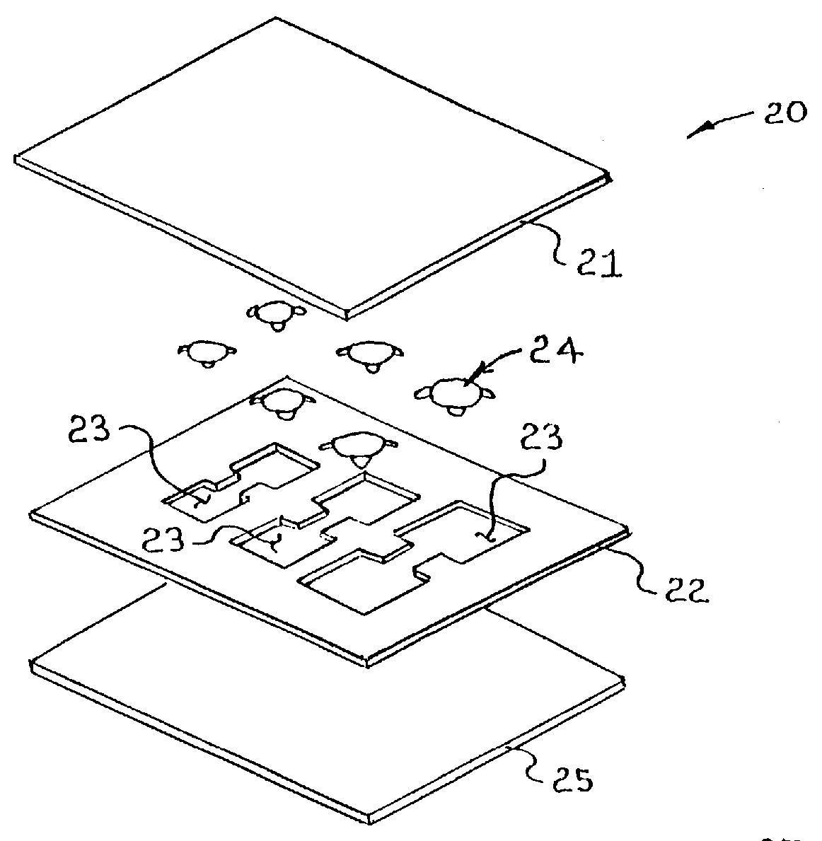
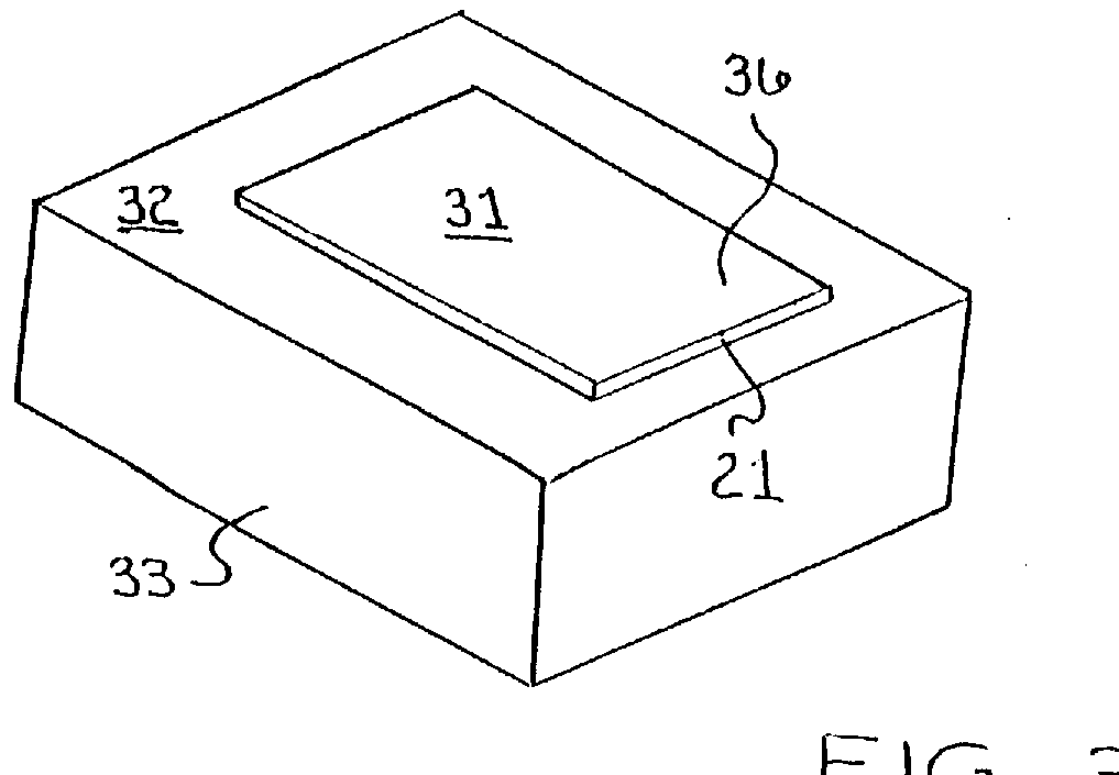
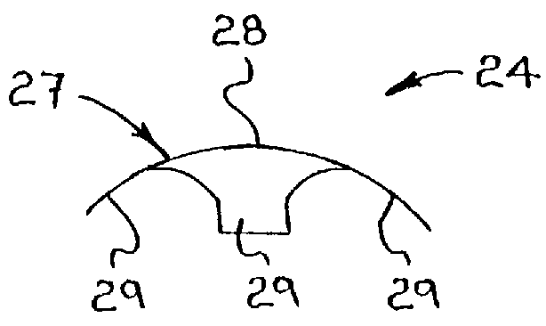
FIG. 1 illustrates the dome switch sub-assembly 20 of the present invention according to a preferred embodiment thereof. Shown is a dome switch sub-assembly 20 consisting of a retaining cover layer 21, a spacer layer 22 having a plurality of spacer layer openings 23 for receiving a plurality of dome switches 24, and a release liner layer 25. The dome switches 24 are sized according to customer size specifications and are manufactured, in well known ways, from approximately 0.09 mm thick stainless steel. In the present invention, FIG. 2 illustrates that the dome switches 24 may be exemplified by a hemispherical surface 27 having an apex 28 at its uppermost portion. Contact tabs 29 are provided along the base of the hemispherical surface 27 for providing an electrical contact with a circuit board 30 (not shown in FIG. 2). Though applicant has described the dome switch 24 according to the best embodiment, it should be apparent to those skilled in the art that other shapes, sizes, and c...


PUM

PropertyMeasurementUnit
thickaaaaaaaaaa
thicknessaaaaaaaaaa
thicknessaaaaaaaaaa

Abstract

A machine method for providing a dome switch sub-assembly used for providing a keyboard-type user input to electronic devices. A spacer layer, attached to a retaining layer, having a plurality of spacer layer openings for receiving a plurality of dome switches is placed upon a moveable machine table. The dome switches, arranged in reel form, are machine removed and placed into the spacer layer openings. A removable release liner is then attached to the spacer layer. Also a complete dome switch assembly is provided. A spacer layer, attached to a circuit board, having a plurality of dome switch openings is placed on a moveable machine table. The dome switches, arranged in reel form, are machine removed and placed into the spacer layer openings. A retaining cover is attached to the spacer layer. An overlay layer, attached to the retaining cover layer, may also be provided.

Description

1. Field of the InventionThis invention relates to a dome switch assembly system. More particularly, this invention concerns the manufacture of a dome switch sub-assembly having a retaining cover, a spacer layer encompassing a plurality of dome switches, and a release liner. Even further, this invention concerns the manufacture of a complete dome switch assembly having a circuit board, spacer layer encompassing a plurality of dome switches, a retaining cover layer, and an overlay layer.2. Description of the Prior ArtTypically, dome switch assemblies or tactile dome switch arrays are utilized to allow a user to manually input data into an electrical device. Generally, such tactile arrays are in the form of a keyboard or touchpad having certain alpha, numerical, or other designations corresponding to a particular area on the tactile array. Upon the user manually pressing these particular areas, dome switches in the array are pressed against a circuit board, thereby allowing an electri...

Claims


Application Information

Patent Timeline
Patent Type & Authority Patents(United States)
IPC IPC(8): H01H13/70
CPCH01H13/7006H01H2205/026Y10T29/49105H01H2229/022Y10T29/49107H01H2205/03
Inventor ODORFER, RICHARD A.
Owner ODORFER RICHARD A
Why Eureka
Try Eureka