Gaseous and liquid fuel injector

a technology of gaseous and liquid fuel and injector, which is applied in the direction of fuel injector, machine/engine, electric control, etc., can solve the problems of increased pollutant emissions, design is not well suited to smaller diesel engines, and there is no pilot fuel

Inactive Publication Date: 2000-06-13
WESTPORT POWER
View PDF13 Cites 162 Cited by
  • Summary
  • Abstract
  • Description
  • Claims
  • Application Information

AI Technical Summary

Problems solved by technology

There appears to be no means for injecting a pilot fuel.
Also, the design is not well suited for smaller diesel engines, as the needle seats are not at the tip of the injector.
This situation is not very important in an engine with high fuel consumption, but it leads to increased pollutant emissions and loss of efficiency in a smaller engine operating from idle to rated speed.
As mentioned above, this design is n

Method used


Image

  • Gaseous and liquid fuel injector
  • Gaseous and liquid fuel injector
  • Gaseous and liquid fuel injector

Examples


first embodiment

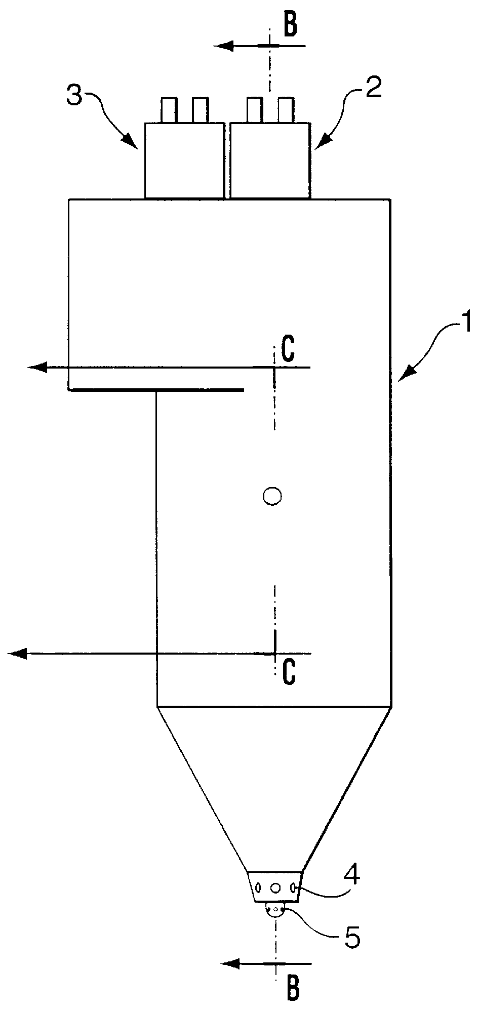
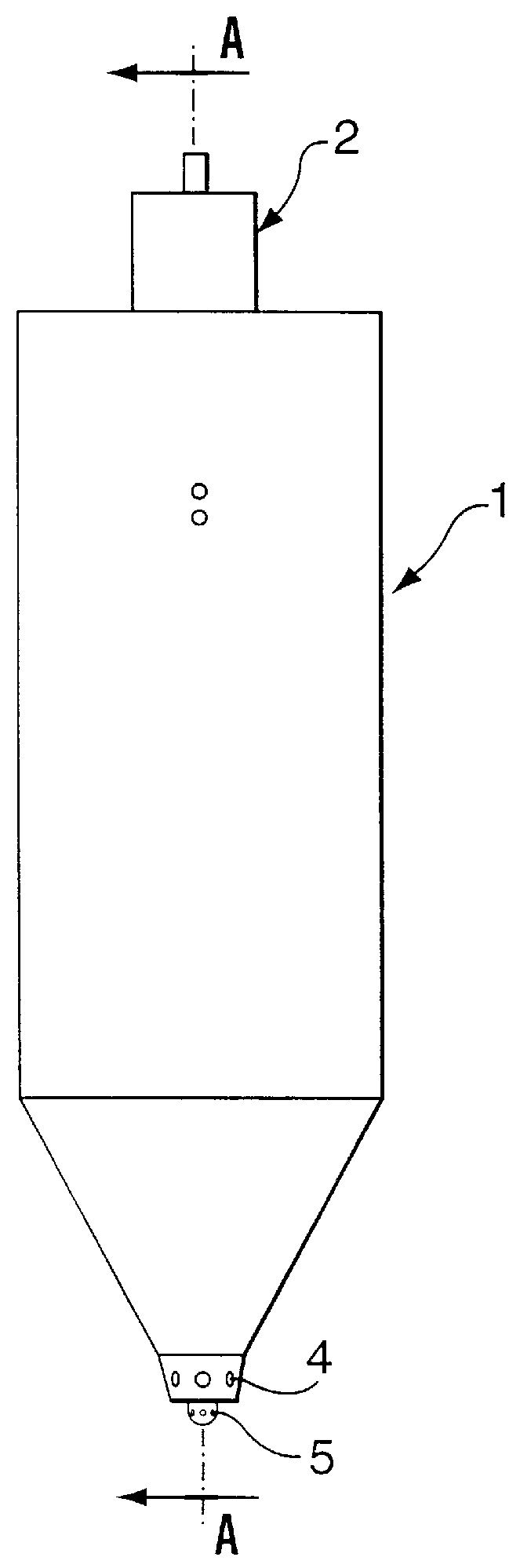
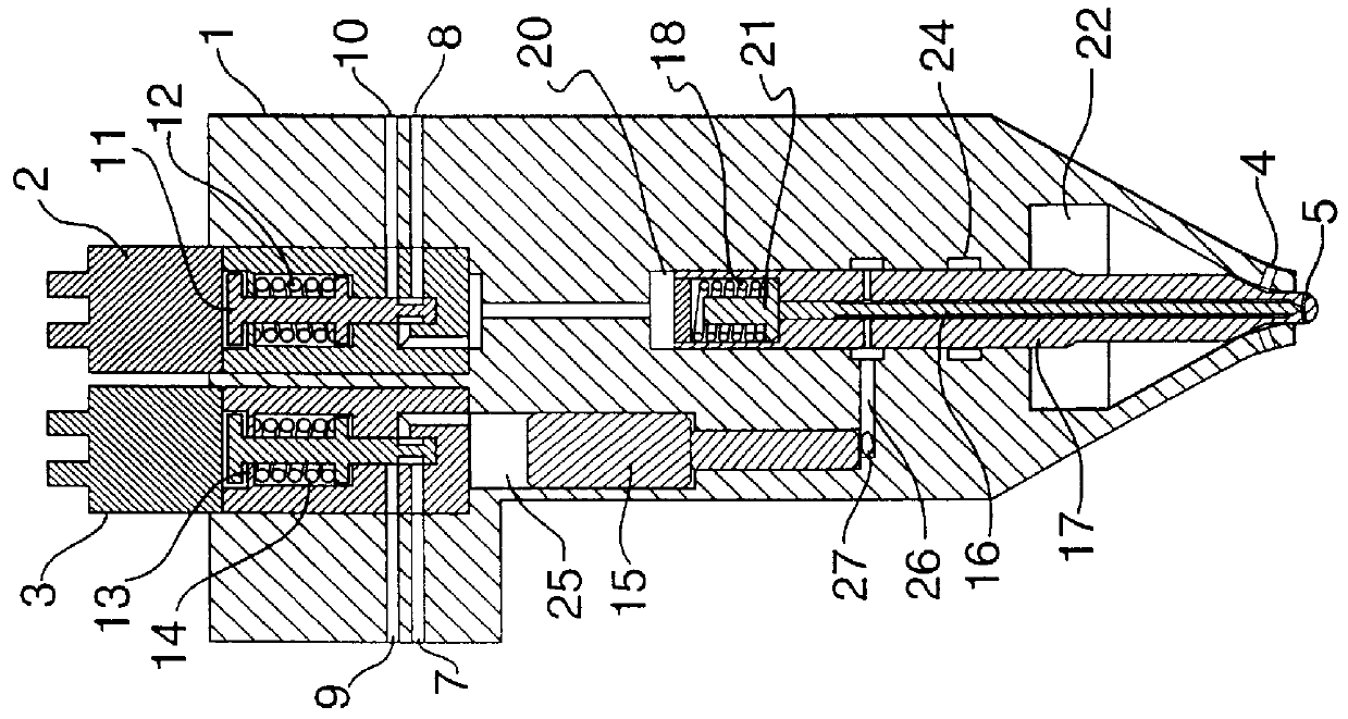
FIGS. 3, 4 and 5 show respectively detail, side and front section views of double solenoid dual fuel injector taken along sections lines C--C, A--A, and B--B shown externally in FIGS. 1 and 2. This embodiment of injector uses high pressure hydraulic fluid to maintain the gaseous fuel valve closed.

FIGS. 3, 4 and 5 illustrate in detail the internal construction of the embodiment 1(a) double solenoid dual fuel injector 1. The injector 1 has three hydraulic fluid inlets 6, 7 and 8, two venting ports 9 and 10, and a gaseous fuel control solenoid 2 and a pilot fuel control solenoid 3 at the top. The injector 1 includes a gaseous fuel control valve 11 and a surrounding gaseous fuel control valve spring 12 positioned below the gaseous fuel control solenoid 2. The injector 1 also includes a pilot fuel control valve 13 and a surrounding pilot fuel control valve spring 14 positioned below the pilot fuel control solenoid 3. In the embodiment presented, valves 11 and 13 are three-way valves and ...

fourth embodiment

FIGS. 9, 10 and 11 show respectively in detail, side and front section views a double solenoid dual fuel injector taken along section lines C--C, A--A and B--B, shown externally in FIGS. 1 and 2. This embodiment is the same as that presented in section 1(a) with the exception of a new pilot fuel inlet 19b, which connects with the underside of intensifier 15 through a check valve 30. The pilot fuel is maintained at a pressure similar to that of the hydraulic fluid.

The operation follows closely that described for embodiment 1(a). When the solenoid 3 is energized, the pressure in cavity 25 falls to drain pressure. The pressure of the pilot fuel introduced through port 19b and through check valve forces the intensifier 15 upward, and pilot fuel fills the volume underneath intensifier 15. Two different pilot metering sequences can be followed as described in embodiment 1(a). The gaseous fuel injection is identical to that described in embodiment 1(a).

2(a) Single Solenoid Gaseous Fuel Val...


PUM


Abstract

A hydraulically actuated dual fuel injector for an internal combustion engine. More particularly, the application pertains to a hydraulically actuated injector for injecting controlled quantities of a first fuel and of a second fuel into an internal combustion diesel engine at different times. A dual fuel injector comprising: (a) an injector body; (b) an inlet port in the injector body for enabling pressurized hydraulic fluid from a hydraulic fluid source to be introduced into the interior of the injector body, the hydraulic fluid being of sufficient pressure to maintain injection valves in the injector body in a closed position until actuated; (c) a first inlet port in the injector body for enabling a first fuel to be introduced into the interior of the injector body; (d) a first injection valve in the injector body connected to the second inlet port for controlling injection of the first fuel from the injector through a first fuel ejection port; (e) a second inlet port in the injector body for enabling a second fuel to be introduced into the interior of the injector body; (f) a second injection valve in the injector body connected to the second inlet port for controlling injection of the second fuel from the injector through a second fuel ejection port; (g) a first control valve which causes the hydraulic fluid to actuate the first injection valve; (h) a second control valve which causes the hydraulic fluid to actuate the second injection valve; (i) a metering device in the injector body for metering the amount of first fuel injected by the first injection valve; and (j) a seal in the injector body which prevents leakage of the second fuel into the first fuel.

Description

This invention relates to a novel hydraulically actuated dual fuel injector for an internal combustion engine. More particularly, the application pertains to a hydraulically actuated injector for injecting controlled quantities of a first fuel and a second fuel into an internal combustion diesel engine at different times.Because of its ready availability, low cost and potential for reducing particulate emissions, natural gas is a promising candidate for fuelling diesel engines. Methods that can be used to convert a diesel engine (a compression-ignition engine) to consume natural gas fall into three categories. One is to convert the engine to a stoichiometric or lean-burn spark-ignition engine. As a second option, the engine can be converted to natural gas using a "dual-fuel" technology, in which the natural gas is mixed with all of or with a portion of the intake air and is ignited by diesel fuel injected at the end of the compression stroke. A third method is the direct injection o...

Claims


Application Information

Patent Timeline
IPC IPC(8): F02M59/00F02M57/00F02M59/10F02M57/02F02M21/02F02M43/00F02M43/02F02M43/04F02M45/08F02M45/00F02M47/02F02D19/10F02D41/20F02D41/38F02M25/00F02M37/00F02M47/00F02M61/04
CPCF02D19/10F02M43/02F02M43/04F02M45/086F02M47/027F02M57/025F02D19/0694F02M21/0263F02M21/0251F02M59/105Y02T10/36Y02T10/32F02M2200/46Y02T10/30
Inventor TOUCHETTE, ALAIN MICHEL JOSEPHDOUVILLE, BRADLEY DONALDBAKER, SIMON MICHAEL
Owner WESTPORT POWER
Why Eureka
Try Eureka