Single pole relay switch

a single-pole relay and switch technology, applied in the direction of relays, contacts, electromagnetic relay details, etc., can solve the problems of unbalanced opening gaps between the two contact sets, undesired shorting between the fixed contacts, and effective arc driv

Inactive Publication Date: 2000-06-13
MATSUSHITA ELECTRIC WORKS LTD
View PDF6 Cites 54 Cited by
  • Summary
  • Abstract
  • Description
  • Claims
  • Application Information

AI Technical Summary

Problems solved by technology

However, this arc drive is effective only when the current flows in one predetermined direction.
That is, when fixed contacts are connected oppositely to flow the current in the direction opposite the predetermined direction, the individual arcs are driven by the magnetic field to stretch towards to e

Method used


Image

  • Single pole relay switch
  • Single pole relay switch
  • Single pole relay switch

Examples


first embodiment figs.1 to 6

First Embodiment FIGS. 1 to 6

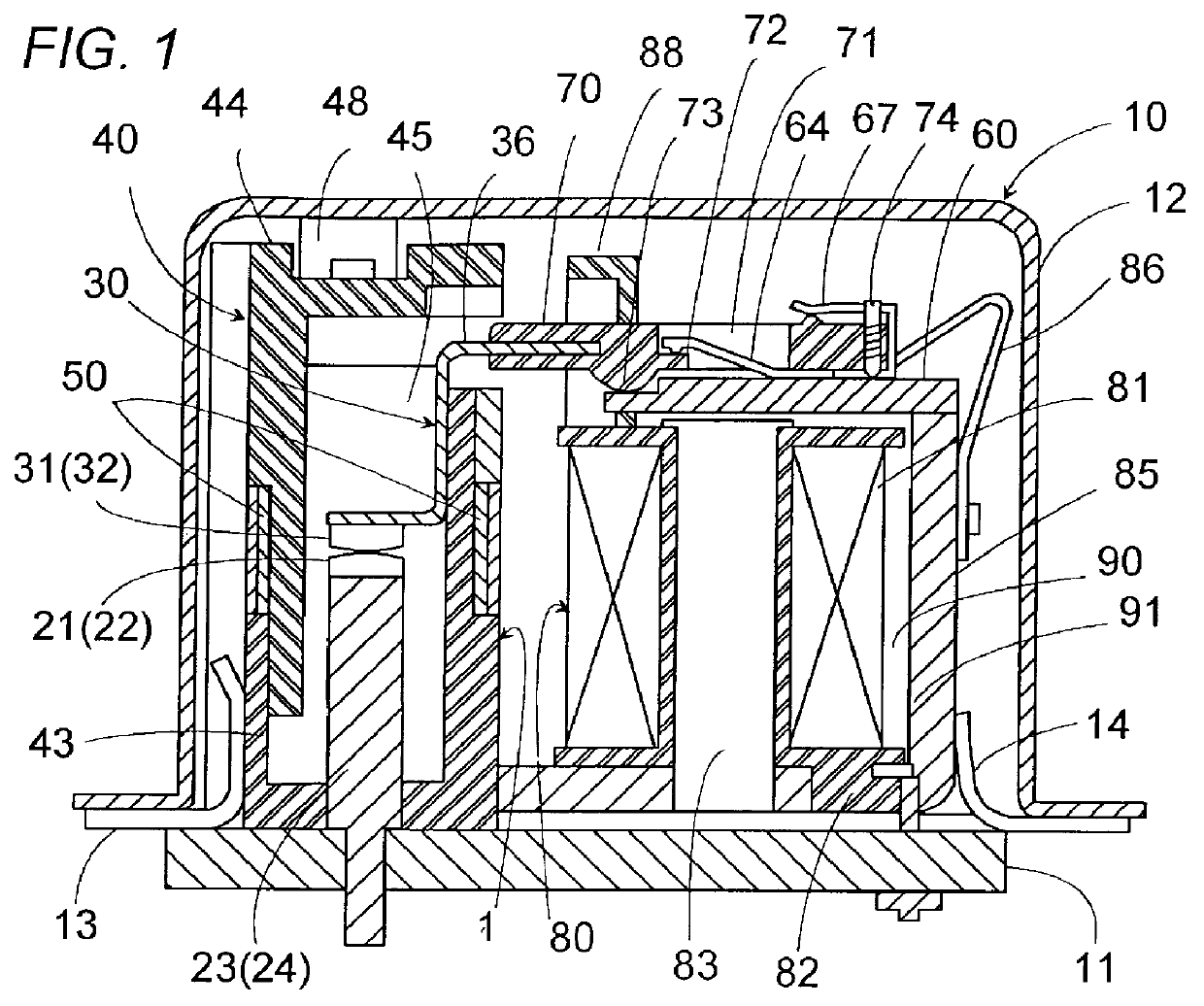
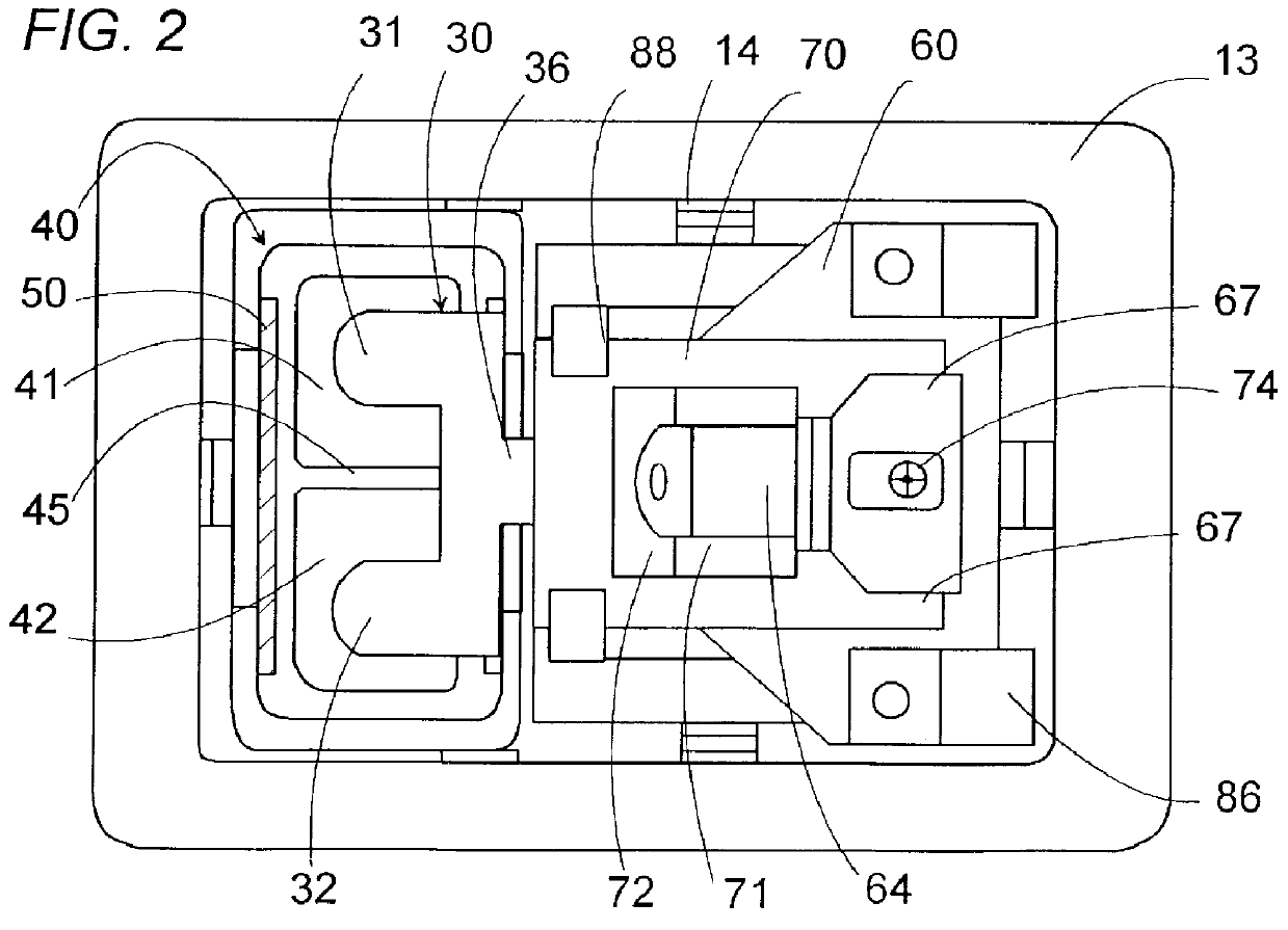
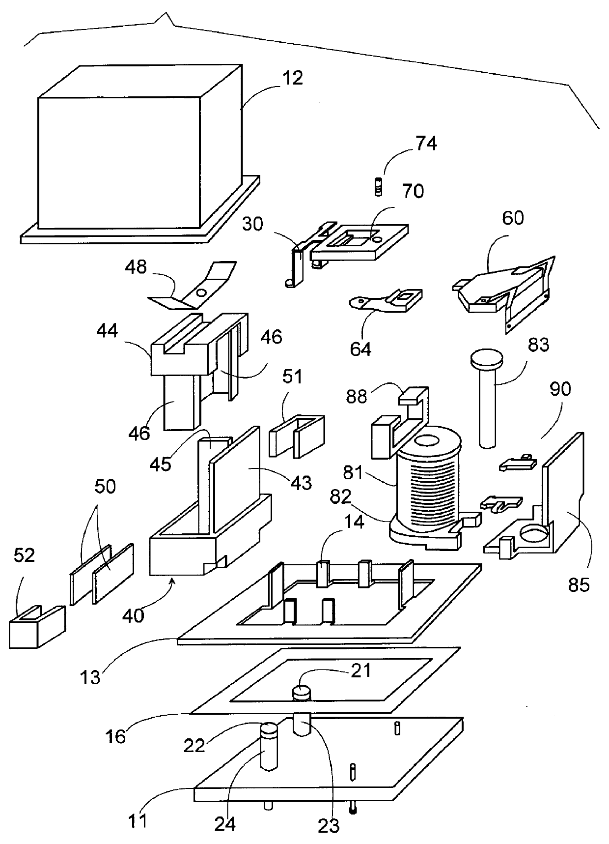
Referring now to FIGS. 1 to 3, there is shown a single-pole relay switch in accordance with a first embodiment of the present invention. The relay switch is utilized, for example, as a high voltage DC power relay or the like for controlling a high electric current. The relay switch has a hermetically sealed housing 10 accommodating therein a contact block 1 and an electromagnet block 80 in a side-by-side relation. The contact block 1 includes a contact carrier 30 having first and second movable contacts 31 and 32 which engage with and disengage from first and second fixed contacts 21 and 22 respectively for conduction and interruption between the first and second fixed contacts. The electromagnet block 80 includes an excitation coil 81 and an armature or actuator 60 which is driven to move the contact carrier 30 into an ON-position of closing the contacts upon energization of the coil 81. A return spring 86 is provided to urge the actuator 60 in the dire...

second embodiment figs.8 to 12

Second Embodiment FIGS. 8 to 12

Referring to FIGS. 8 to 12, there is shown a single-pole relay switch in accordance with a second embodiment of the present invention, which is identical to the first embodiment except that a contact carrier 30A is pivotally supported to a header 170 of an actuator 60A. Like parts are designated by like numerals with a suffix letter of is "A". A like over-travel spring 64A extends from the actuator 60A of electromagnet block to the header 170 of a dielectric material with the rear end of the spring secured to the actuator 60A and with the front end of the spring fixedly inserted to the header 170. The header 170 is formed to have a horizontally extending slit 171 for connection with a prop 36A of the contact carrier 30A. As shown in FIG. 11, a ball-shaped projection 172 is formed on an upper wall of the slit at a longitudinal center of the slit 171 and projects into a round-hole 37 in the prop 36A of the contact carrier 30A to give a swivel joint by wh...


PUM


Abstract

A single-pole relay switch capable of effective arc extinction irrespective of the current flowing directions in which the device is connected in a circuit. The switch has a housing and two sets of contacts located in the housing, each set being composed of a fixed contact and a movable contact. A contact carrier is provided to have first and second movable arms which extend commonly from a bridge and are provided respectively with the two movable contacts. An actuator applies a driving force to move the contact carrier between an ON-position of holding the movable contacts simultaneously in contact respectively with the fixed contacts, and an OFF-position of keeping the movable contacts at respective opening gaps from the fixed contacts. The housing includes a casing which is divided into first and second chambers respectively for receiving the contact sets, each of the first and second chambers being surrounded by a dielectric wall. Permanent magnet are disposed around the casing to stretch the individual arcs in opposing directions to each other and towards the dielectric walls of the first and second chambers, respectively. Thus, the individual arcs can be stretched individually within the separate chambers, i.e., in an isolated condition. Therefore, the individual arcs can be free from merging even when the current flows in such a direction as to drive the arcs in the approaching direction.

Description

1. Field of the InventionThe present invention is directed to a single-pole relay switch, and more particularly to a relay switch with a pair of fixed contact which are conducted with or interrupted from each other by a common movable member in an arc-extinguishing environment.2. Description of the Prior ArtU.S. Pat. No. 5,892,194 discloses a contact device with a pair of fixed contacts which are closed and opened by a common movable contact within a sealed compartment of an elongated configuration. The fixed contacts are spaced along the length of the compartment and form a pair of two parallel opening paths or gaps with the movable contact moving away from the fixed contacts. Permanent magnets are disposed around the compartment to generate a magnetic field which drives arcs each extending between the movable contact and the fixed contacts for stretching arcs in opposite directions of moving the individual arcs away from each other towards the opposite end walls of the compartment...

Claims


Application Information

Patent Timeline
IPC IPC(8): H01H9/30H01H50/54H01H50/00H01H50/64H01H9/44H01H1/34H01H1/12H01H9/34
CPCH01H50/645H01H50/54H01H9/443H01H1/34H01H9/34
Inventor UOTOME, RIICHITOGUCHI, TAKEHIKOYAMAMOTO, RITSUITO, MASAHIROHOSHINO, NARUTOSHI
Owner MATSUSHITA ELECTRIC WORKS LTD
Why Eureka
Try Eureka