Mechanized foldable bed

a foldable bed and folding technology, applied in the field of mechanized foldable beds, can solve the problems of complex structure and high cos

Inactive Publication Date: 2000-06-20
MODAS SHING
View PDF3 Cites 48 Cited by
  • Summary
  • Abstract
  • Description
  • Claims
  • Application Information

AI Technical Summary

Problems solved by technology

However, the operation of this type of bed requires that a person not in the bed manually turn the handle to adjust the bed.
The co...

Method used


Image

  • Mechanized foldable bed
  • Mechanized foldable bed
  • Mechanized foldable bed

Examples


Embodiment Construction

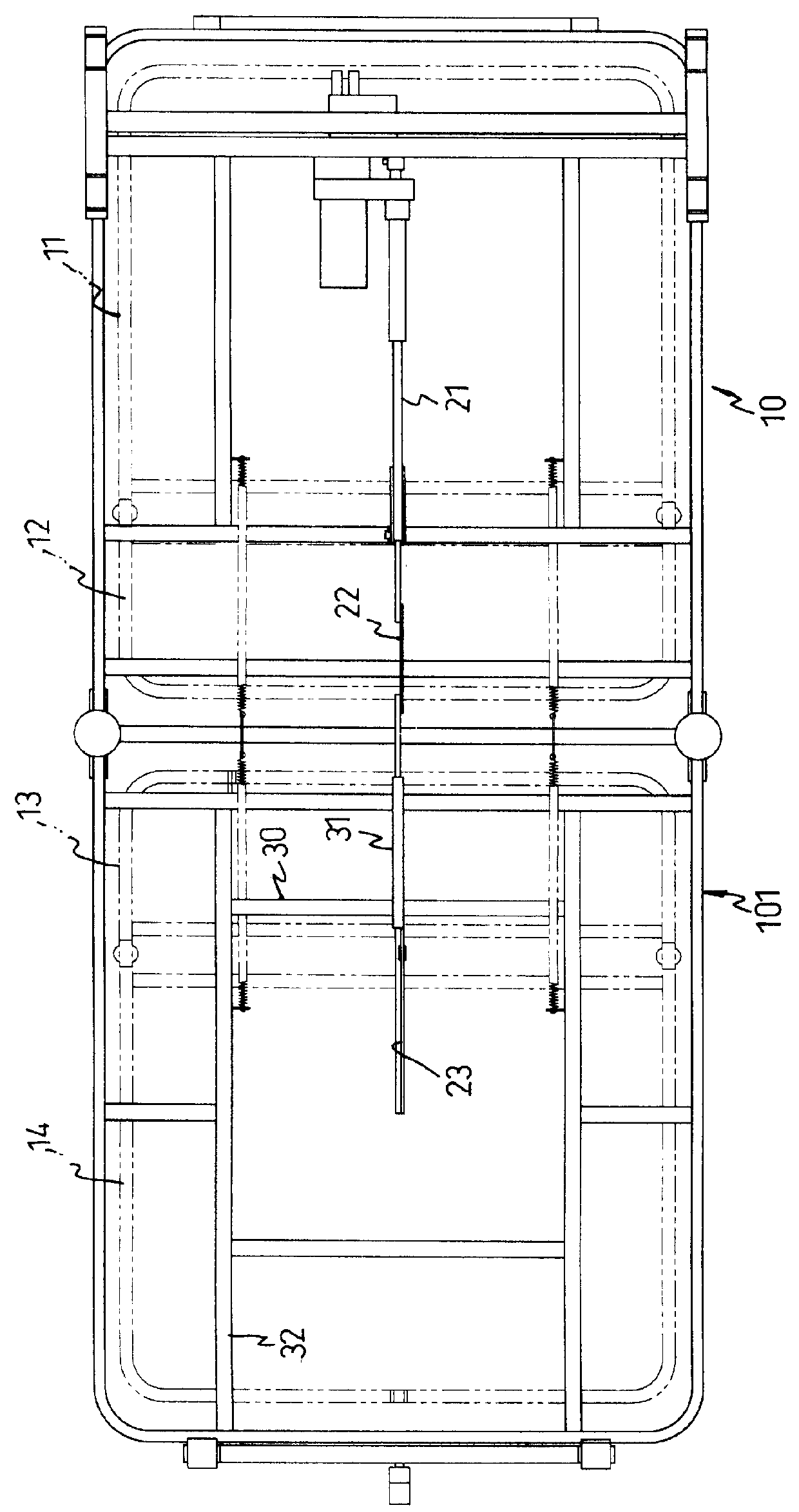
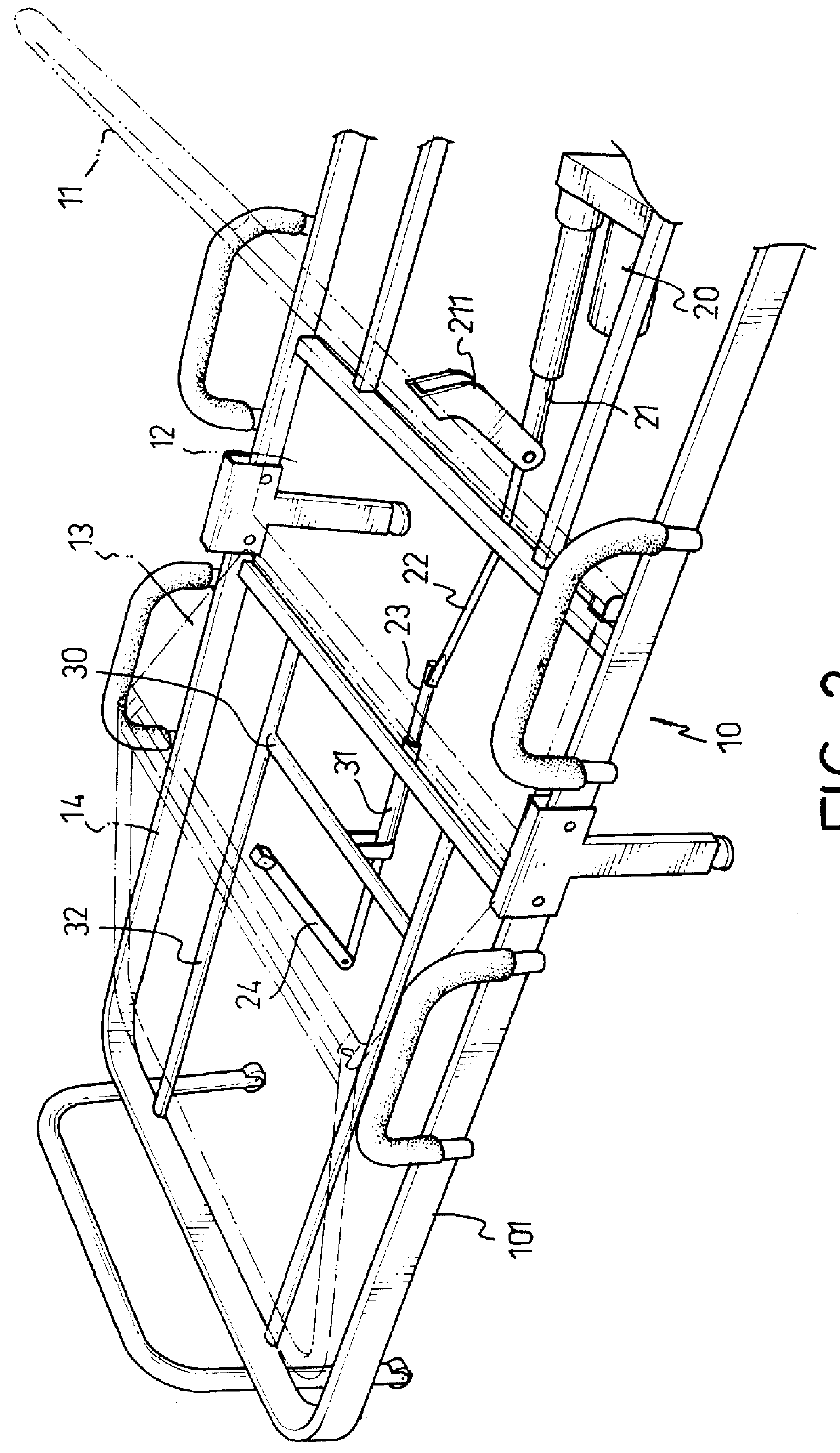
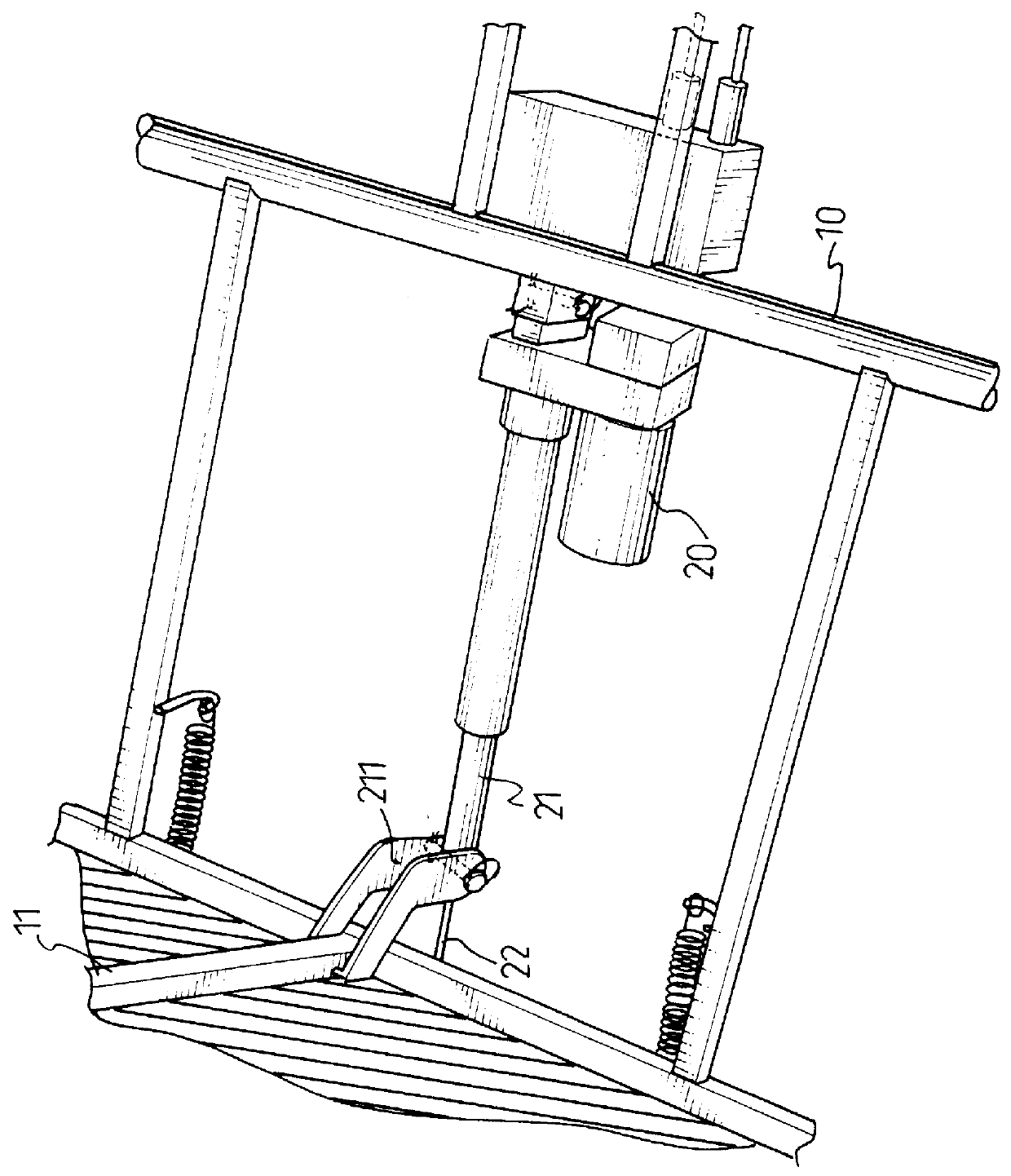
The present invention relates to a mechanized foldable bed. Referring to FIGS. 1 and 2, the foldable bed has a front frame assembly (10) composed of a first frame member (11) and a second frame member (12) pivotally connected with the first frame member (11) and a rear frame assembly (101) composed of a third frame member (13) and a fourth frame member (14) pivotally connected with the third frame member (13). Furthermore, the foldable bed has a motor (20), a driving rod (21) extendably connected with the motor (20), a first connecting rod (22) pivotally connected with the driving rod (21), a second connecting rod (23) pivotally connected with the first connecting rod (22) and a tube (31) securely mounted under the rear frame assembly (101) for receiving the second connecting rod (23) therethrough. The first frame member (11) has a first connector (211) securely connected thereunder and pivotally connected with the driving rod (21). The third frame member (13) has a second connector...


PUM


Abstract

A mechanized foldable bed is disclosed. The foldable bed has a front frame assembly and a rear frame assembly pivotal with respect to the front frame assembly. A motor is securely mounted under the bed, a driving rod is driven by the motor, a first connecting rod is pivotally connected with the driving rod and a second connecting rod is pivotally connected with the first connecting rod. A tube securely mounted under the bed is for receiving the second connecting rod therethrough. Furthermore, due to a first connector securely connected with the front frame assembly and pivotally connected with the driving rod and a second connector pivotally between the rear frame assembly and the second connecting rod, the torso and legs of a patient are supported simultaneously.

Description

1. Field of the InventionThe present invention relates to a mechanized foldable bed, and more particularly to the structure that provides substantial support to a user lying on the bed. The structure uses a single motor and a series of linkages pivotally connected with the motor so as to simultaneously provide support to the torso and legs of the user.2. Description of Related ArtA lot of patents addressing the function and structure of a bed for hospital patients are available to the public. Functionally, these beds all have one thing in common, that is to provide support to the torso and legs of a patient lying thereon. Normally, a foldable bed used for a patient has a handle, a shaft connected with the handle and a plurality of linkages pivotally connected with the shaft. When the handle is rotated, the shaft with thread formed thereon will be driven to rotate in the same direction as the handle. The rotation of the shaft will thus drive the rear portion and / or the front portion ...

Claims


Application Information

Patent Timeline
IPC IPC(8): A47C19/12A47C20/04A47C20/00A47C19/00A61G7/015A61G7/002
CPCA47C19/122A61G7/015A47C20/041
Inventor WU, JACK
Owner MODAS SHING
Why Eureka
Try Eureka