Ground-engaging shoe assembly for a power mower

Inactive Publication Date: 2000-06-20
GUMMERSON ELWYN
View PDF18 Cites 11 Cited by
  • Summary
  • Abstract
  • Description
  • Claims
  • Application Information

AI Technical Summary

Benefits of technology

By yet a further feature of the ground-engaging shoe includes a ground-engaging endless belt entraining a forward freely-rotatable roller and a rear freely-ro

Problems solved by technology

This constant manoeuvring can be nauseating, tiring and time consuming.
The suspension mechanism of such rotary mower structure was designed to

Method used


Image

  • Ground-engaging shoe assembly for a power mower
  • Ground-engaging shoe assembly for a power mower
  • Ground-engaging shoe assembly for a power mower

Examples


Embodiment Construction

(i) Aims of the Invention

In spite of these prior patents, there is still a need for a ground-engaging shoe assembly for a power mower in which a mower blade is rotated in an upright shaft.

(ii) Statement of Invention

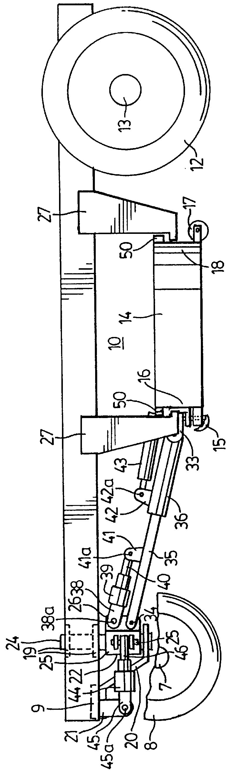
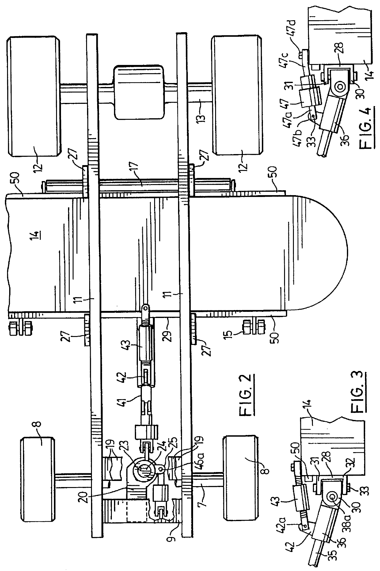
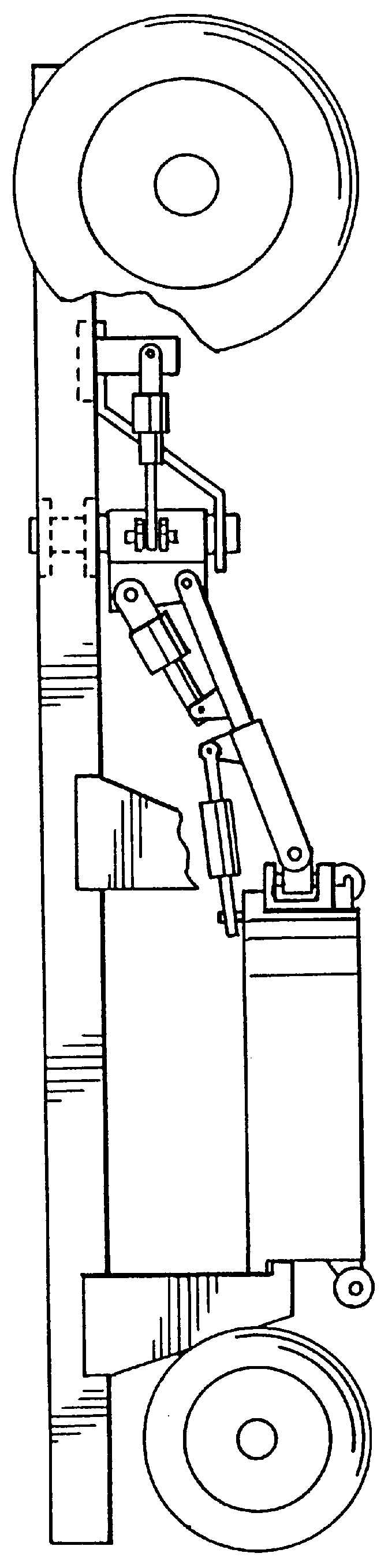
The present invention provides a ground-engaging shoe assembly for a mower housing for a power mower in which a mower blade is rotated or an upright shaft. The ground-engaging shoe includes a hub support assembly which is secured to the mower housing of the power mower. A bearing housing is provided which is adapted selectively to accept different ground-engaging shoes, to which the selected ground-engaging shoe is adapted to be quickly installed, exchanged and secured. A ground-engaging shoe is secured to a lower face of the bearing housing, the bearing housing including a bearing within which the hollow shaft rotates, whereby the ground-engaging shoe assembly is stationary. An adjusting bolt extends through the hollow shaft and is secured at its lower end to the bearing...


PUM


Abstract

A ground-engaging shoe assembly is provided for a power mower in which a mower blade is rotated in an upright shaft. The ground-engaging shoe includes a hub support assembly which is secured to the mower housing of the power mower. A ground-engaging shoe assembly is secured to a bearing housing which is located at the lower end of a hollow rotatable shaft, the ground-engaging shoe assembly including a bearing within which the hollow shaft rotates, whereby the ground-engaging shoe assembly is stationary. The bearing housing is adapted selectively to accept different ground-engaging shoes. An adjusting bolt extends through the hollow shaft and is secured at its lower end to the bearing housing An upper tower housing is adapted to transfer loading weight through the adjusting bolt to the bearings. The adjusting bolt is vertically-adjustably-secured at its upper end with respect to the upper tower housing by means of a locking-type nut. Thus, the cutting height of the mower blade is adjusted by loosening the locking-type nut, and by turning the adjusting bolt, e.g., by means of a slot at its upper end, thereby safely and easily adjusting the height of the mower blade by raising or lowering the ground-engaging shoe.

Description

(ii) Field of the InventionThis invention relates to a ground-engaging shoe assembly for a power mower in which a mower blade is rotated in an upright shaft.(iii) Description of the Prior ArtGrass cutting mower attachments for a vehicles are known,in which the grass cutting mower attachment being operated to move quickly laterally to the right or to the left of the vehicle and / or up or down vertically with respect to the vehicle. Up to the present time the most versatile grass cutting machines require the operator to move the complete vehicle in a series of manoeuvres around obstacles. This constant manoeuvring can be nauseating, tiring and time consuming. There are now a number of mower devices which have been adapted for mounting on vehicles and include some form of retraction and extension apparatus for moving the mowers or saws towards and away from the vehicle. Some such retractable mower devices are shown in U.S. Pat. No. 2,719,081, issued to Allen et al, U.S. Pat. No. 2,662,5...

Claims


Application Information

Patent Timeline
IPC IPC(8): A01D34/00A01D34/66A01D34/64A01D34/63A01D34/86
CPCA01D34/64A01D34/661A01D34/863Y10S56/03A01D2101/00Y10S56/10
Inventor GUMMERSON, ELWYN
Owner GUMMERSON ELWYN
Why Eureka
Try Eureka