Self-actuated off-center subreflector scanner

a subreflector scanner and self-actuation technology, applied in the direction of antennas, electrical equipment, etc., can solve the problems of reducing reliability and complicated systems, and achieve the effect of reducing reliability, facilitating search and acquisition

Inactive Publication Date: 2000-06-20
L 3 COMM CORP
View PDF3 Cites 8 Cited by
  • Summary
  • Abstract
  • Description
  • Claims
  • Application Information

AI Technical Summary

Benefits of technology

However, when the motor is turned on and the sub-reflector rotates, the forces generated by the rotation cause the sub-reflector to shift to and remain in a position that is offset from the rotating shaft of the motor, which shift in position, in turn, causes the sub-reflector to be offset from, and to revolve about, the optical axis of the antenna. The consequent scanning of the antenna beam about the central axis of the antenna facilitates the search for, and acquisition of, the satellite. By using the rotational forces, instead of using an electrical solenoid to shift the sub-reflector into the offset position, this invention avoids any need for brushes and a commutator for connecting to a solenoid that would be located on the spinning subreflector and used to shift the position of the subreflector or any need for thrust bearings and shift mechanisms that would be required if the solenoid were located elsewhere. Any such brushes and commutator or thrust bearings and shift mechanisms would complicate the system and likely degrade its reliability.

Problems solved by technology

Any such brushes and commutator or thrust bearings and shift mechanisms would complicate the system and likely degrade its reliability.

Method used


Image

  • Self-actuated off-center subreflector scanner
  • Self-actuated off-center subreflector scanner
  • Self-actuated off-center subreflector scanner

Examples


Embodiment Construction

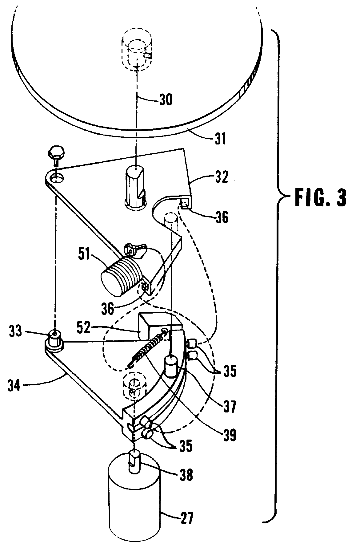
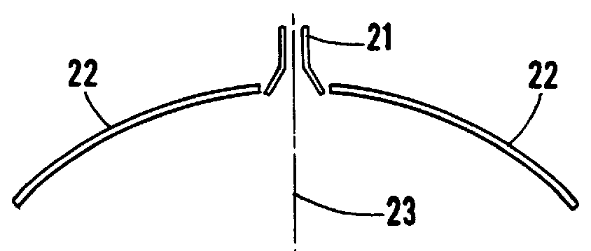
FIG. 2 is a schematic depiction of the preferred embodiment of the invention consisting of an antenna feed 21, a main reflector 22 having an central, optical axis 23, a subreflector 24, and a shiftable mounting mechanism 25 that is mounted on drive shaft 26, which shaft is driven by motor 27. When the motor is not operating, the shiftable mounting mechanism 25, together with one or more springs or other position restoring mechanism within the shiftable mounting mechanism 25 causes the subreflector to be aligned with the central, optical axis 23. When the motor is turned on, it causes shaft 26 and shiftable mounting mechanism 25 and subreflector 24 to rotate. In the preferred embodiment, the mounting mechanism and subreflector rotate at approximately 10 hertz. Shiftable mounting mechanism 25 allows the position of subreflector 24 to shift in response to the forces generated by the rotation such that the axis of subreflector 24 is offset from axis 23 and revolves about axis 23, thus c...


PUM


Abstract

An optical reflector antenna utilizes a subreflector that is offset from the optical axis of the antenna and that revolves about the optical axis to scan the beam from the antenna in a circular path about the axis of the antenna to facilitate the search for and acquisition of a satellite for subsequent tracking and communications. The subreflector is mounted on a rotatable shaft that is aligned with the optical axis of the antenna. When the shaft is not being rotated, one or more springs hold the subreflector in a fixed position aligned with the optical axis of the antenna to facilitate tracking and communications. When the shaft is rotated, rotational forces cause the subreflector to shift to and remain at a position that is offset from the optical axis and the rotation of the shaft causes the offset subreflector to revolve about the optical axis of the antenna, thus scanning the beam from the antenna to facilitate the search for and and the acquisition of the satellite.

Description

1. BACKGROUND OF THE INVENTIONa. Field of the InventionThis invention pertains to optical, reflector antennas. More particularly this invention pertains to the scanning of the beam from a reflector antenna by using a subreflector that is offset from the optical axis of the reflector antenna and revolves about that axis.b. Description of the Prior ArtMany optical, radio-frequency antennas, such as the cassegrainian antenna depicted in FIG. 1 utilize a feed 11, a main reflector 12 and a subreflector 13 to generate a narrow, pencil-shaped beam aligned with the centerline or optical axis 14 of the antenna. Such antennas are used for many purposes such as communicating with, and for the tracking of, earth satellites. However, in instances where the initial position of the satellite is not well known, the antenna must first search for and find the position of the satellite in order to "lock-on to" or acquire and begin tracking the satellite. Unfortunately, the narrow, pencil-shaped beam t...

Claims


Application Information

Patent Timeline
Patent Type & Authority Patents(United States)
IPC IPC(8): H01Q3/20H01Q3/00
CPCH01Q3/20
Inventor WETTER, JR., PIERCE T.
Owner L 3 COMM CORP
Why Eureka
Try Eureka