Windproof umbrella structure

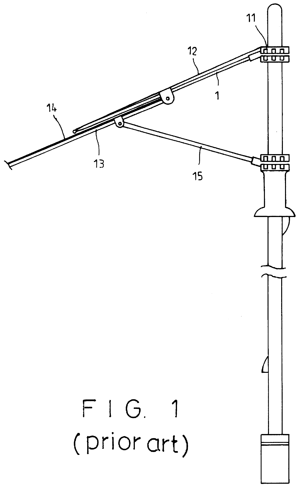
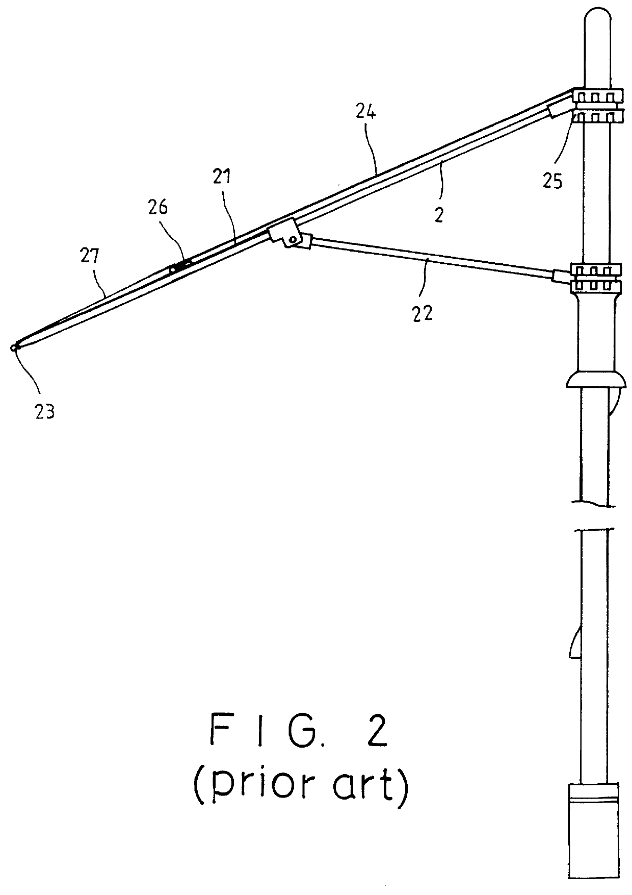
a technology of umbrella structure and umbrella rib, which is applied in the direction of umbrellas, traveling accessories, apparel, etc., can solve the problems of only extending the rib (1), the strength of the umbrella is therefore not enough, and the second rib (13) is easily broken by the wind pressure, so as to achieve the effect of improving strength and improving strength

Inactive Publication Date: 2000-07-18
KO CHIN SUNG
View PDF6 Cites 32 Cited by
  • Summary
  • Abstract
  • Description
  • Claims
  • Application Information

AI Technical Summary

Benefits of technology

The main object of the present invention is to provide an improved windproof umbrella structure with novel assembly of the umbrella cover and the ribs of the frame, which obtains a better strength and improvement.

Problems solved by technology

The drawback of this umbrella is that the main rib (1) only extends to the board of the upper cover (12).
The strength of the umbrella is thus not enough that the second rib (13) might be easily broken by the wind pressure.
The drawback of the design is that the upper cover (25) is connected with the end (23) of the main rib (2) by the wires (27) only and the strength of the umbrella is still not enough for avoiding damage.

Method used


Image

  • Windproof umbrella structure
  • Windproof umbrella structure
  • Windproof umbrella structure

Examples


Embodiment Construction

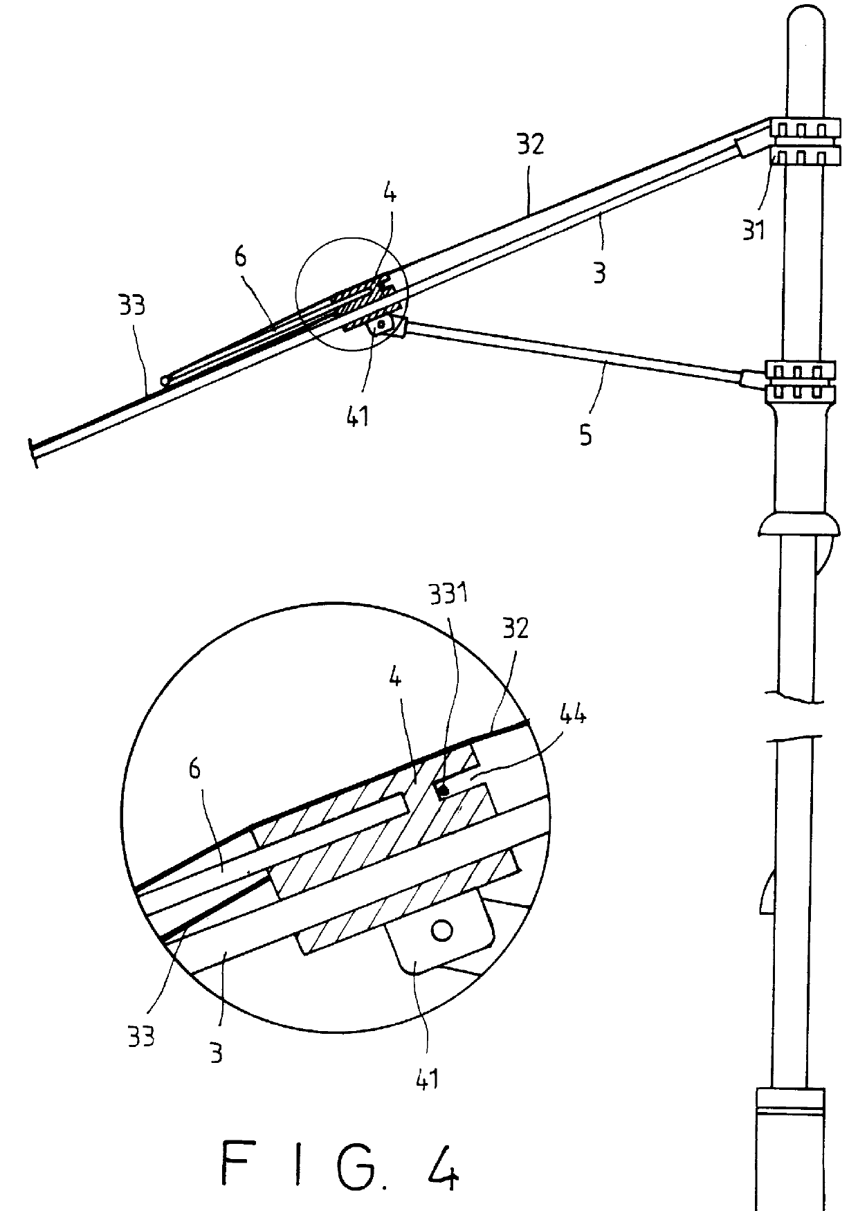
Please refer to FIGS. 3 to 5, the present invention includes a main rib (3) having an inner end pivoted on a notch (31) of the umbrella shaft and connecting with a connector (4) at the middle position. A stretcher (5) has its out end pivoted with a slice (41) of the connector (4). The connector (4) has a central hole (42) for receiving the main rib (3) and has a groove (43) for engaging a second rib (6) therein, and a slot (44) on the other side relating to the groove (43).

The upper cover (32) covers the middle place of the frame and connects the board with the second rib (6), that provides a better connecting strength. The lower cover (33) is provided with several inner rings (331) for hanging at the slot (44) of the connector (4) in convenience. The board of the lower cover (33) can be connected with the ends (35) of the main ribs (3).

In use, when the upward wind occurs, the airflow as the arrows in FIGS. 6 and 7, blows to the bottom side of the upper cover (32) that may force the...


PUM


Abstract

A windproof umbrella structure includes mainly a connector being provided at a pivoted position of the main rib and the stretcher to engage with a second rib. The invented assembled frame is covered by an upper cover and a lower cover and obtains a better umbrella strength. When the upward wind occurs, the airflow can pass through the gap between the two covers for avoiding the damage of the ribs.

Description

In order to prevent from damage of the umbrella when it occurs upward wind, there are some designs with double covers on the frame of the umbrella, which can release pressure for avoiding the ribs of the frame being unusually folded and broken. As shown in FIG. 1, it can be seen that a prior known windproof umbrella includes a main rib (1) extending outsides from the upper notch (11) and being covered with an upper cover (12). A second rib (13) is pivoted on the main ribs (1) at a middle bottom position, while a lower cover (14) is covered on the second rib (13). A stretcher (15) has the outer end to pivot with the second rib (13). When the upward wind occurs, the main rib (1) and the second rib (13) are capable of changing the related position by the wind pressure and the airflow can pass through between the two covers (12), (14). The drawback of this umbrella is that the main rib (1) only extends to the board of the upper cover (12). The lower cover (14) is supported by the second...

Claims


Application Information

Patent Timeline
Patent Type & Authority Patents(United States)
IPC IPC(8): A45B25/00A45B25/02A45B25/22
CPCA45B25/02A45B25/22A45B2025/186
Inventor KO, CHIN-SUNG
Owner KO CHIN SUNG
Why Eureka
Try Eureka