Security device for a movable closure and method therefor

a security device and movable technology, applied in the direction of wing accessories, carpet fasteners, mechanical devices, etc., can solve the problems of insufficient strength and/or ingenuity of intruders, padlocks or other locks that are subject to unauthorized manipulation, and garage door openers that provide little security, etc., to achieve the effect of convenient operation and easy installation

Inactive Publication Date: 2000-07-18
GARAGE PROTECTION SYST
View PDF21 Cites 94 Cited by
  • Summary
  • Abstract
  • Description
  • Claims
  • Application Information

AI Technical Summary

Benefits of technology

It is another object of this invention to provide a security device and method therefor that conveniently secures a movable closure which is movable by a mechanical opening element.
The present invention provides the benefits to the user of the ability to remotely operate the securing device and the ability to operate the securing device in conjunction with an automatic device for opening and closing the closure. The actuator of the present invention may be energized by an electrical signal which causes the actuator element to move from its first position to its second position. This electrical signal may come from a radio frequency remote control, as is well-known in the art. Further, the radio frequency signal may also activate an automatic opening device. Thus, when the automatic opening device is activated, the actuator of the securing device can also be activated so that the closure can be unsecured and be automatically opened with the opening device with the same remote control signal.

Problems solved by technology

These padlocks are generally located on the outside surface of the garage door and are, therefore, subject to unauthorized manipulation.
Padlocks or other locks often have proven insufficient to overcome the strength and / or ingenuity of an intruder.
Further, garages having garage door openers provide little security and often sacrifice security for convenience.
For example, the currently available garage door locks may not provide adequate security against an unauthorized entry.
Other garage door locks may be overly complex and require delicate adjustments and constant maintenance in order to function reliably.
Others are inconvenient in that they are not capable of being opened using a remote control, and thus do not take advantage of such technology.

Method used


Image

  • Security device for a movable closure and method therefor
  • Security device for a movable closure and method therefor
  • Security device for a movable closure and method therefor

Examples


second embodiment

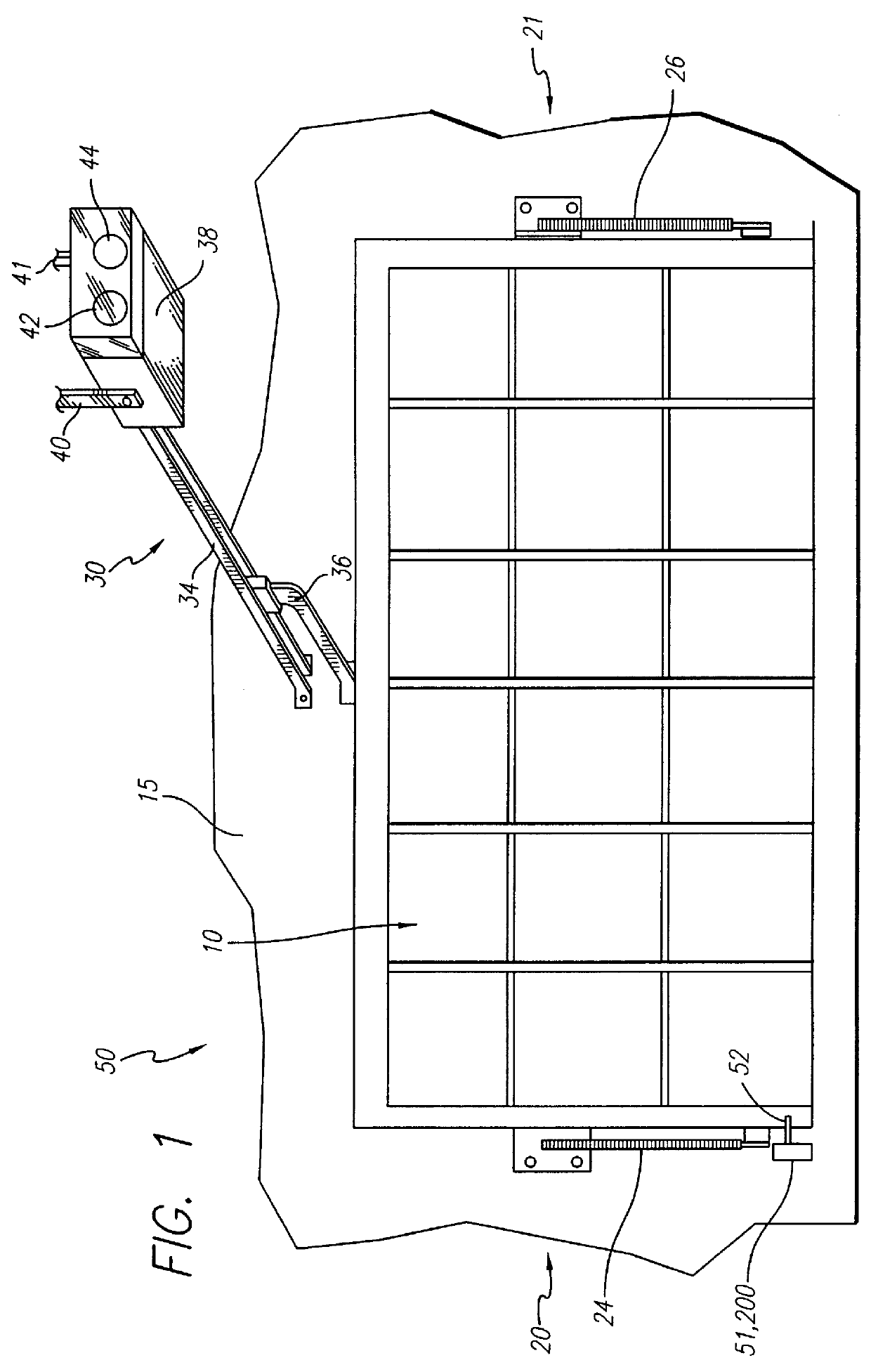
Referring now to FIGS. 5-16, the security device 50 is shown. The security device 50 comprises a mounting bracket 202, locking assembly 200, and securing element 201. The mounting bracket 202, which has screw holes 204 and bolt holes 206, can be mounted onto the support frame 15 with screws (not shown) through the screw holes (see FIG. 6). The locking assembly 200 is attached to the mounting bracket 202 by a first 246, second 248, and third bolt 250 and by nuts 251.

The corresponding securing element 201 comprises a base 208, a U-shaped bracket 210, and a rod 212. The securing element 201 is mounted onto the side edge of the garage door 10 by screws (not shown), and the locking assembly 200 engages and disengages with the rod 212.

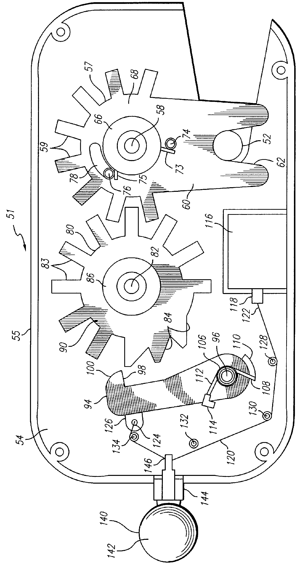
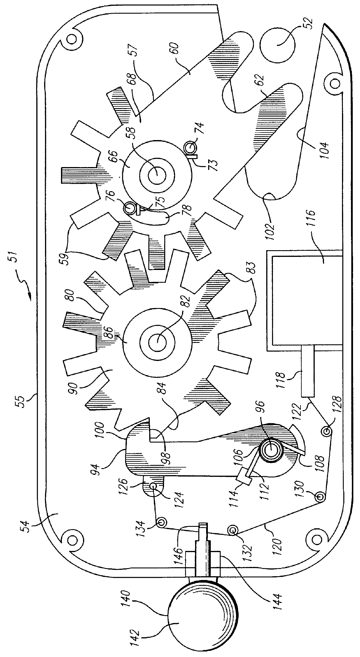
The mechanism of the locking assembly 200 is housed in a bottom 214 and top case 216 (see FIGS. 7 and 8). The bottom case 214 has a base 218 which includes a first 220, second 222, and third shaft 224. Each of these shafts 220, 222, 224 includes a first 226,...

third embodiment

FIG. 22 is a block diagram of a preferred embodiment of the electronics which control the security device 50 described for a garage door 10 equipped with a garage door opener 30. The electronics module 150' includes an AC to DC power transformer 152', a radio frequency receiver 154', a timer element 156', a garage door opener relay 410, and a solenoid relay 158'. The electronics module 150' is coupled to the garage door opener 30', a garage door opener button 46', the locking assembly 200', and the radio frequency transmitter 162'. The AC to DC power transformer 152' is connected to a power supply such as a standard electrical outlet 153' or the light bulb socket of the garage door opener 30. Alternative power sources such as a battery may also be used.

The preferred embodiment may further include a second locking assembly 412 which can be mounted on the support frame 15 to further secure the garage door 10. The second locking assembly 412 is essentially the same as the locking assem...


PUM


Abstract

A method and apparatus for selectively securing and unsecuring a movable closure to a support frame is provided. The security device of the present invention comprises a locking assembly attached to the frame and a securing element attached to the closure. The locking assembly comprises a first rotating element having a detent, a second rotating element being engaged with the first rotating element, and a rotating latching element being selectively engageable with the second rotating element. When the movable closure is secured, the detent of the first rotating element is securely coupled with the securing element.

Description

This invention generally relates to an apparatus and method for securing a movable closure, and relates in particular, to an apparatus and method for securing a movable closure such as a door to its support frame. The invention is applicable, but not limited to, movable closures that are connected to an opening mechanism which moves the closure from its closed position to an opened position, and to closures that are manually moved from their closed position to an opened position.A typical garage door assembly includes a solid door pivotally mounted in a door frame. From a closed position, the door can move pivotally upwardly and rearwardly to an overhead, approximately horizontal position. Another type of garage door assembly includes a garage door partitioned into several members. These several members are guided by rollers connected to a track system.Various methods exist today for securing such garage doors to prevent any unauthorized entry by an intruder into the garage. Many re...

Claims


Application Information

Patent Timeline
Patent Type & Authority Patents(United States)
IPC IPC(8): E05B47/06E05B65/00E05F15/16E05C3/24E05C3/00
CPCE05B47/0002E05B47/0607E05B65/0021E05B47/0004E05F15/668E05Y2201/22E05Y2900/106Y10S292/36Y10S70/11E05C3/24Y10T292/1047Y10T292/1082
Inventor SHOEMAKER, RODNEY
Owner GARAGE PROTECTION SYST
Why Eureka
Try Eureka