Method for the manufacture or repair of a blisk by linear friction welding

a technology of friction welding and manufacturing method, which is applied in the direction of manufacturing tools, machines/engines, turbines, etc., can solve the problems of three-dimensional and complex footprint of blades on disk surfaces, inability to accept material wastage, and high cost of solid machining

Inactive Publication Date: 2000-08-01
ROLLS ROYCE PLC
View PDF15 Cites 79 Cited by
  • Summary
  • Abstract
  • Description
  • Claims
  • Application Information

AI Technical Summary

Problems solved by technology

Machining from solid is expensive and inevitably results in an unacceptable wastage of material, especially in the case of larger BLISKs.
Furthermore, this surface may also be concave or convex and i

Method used


Image

  • Method for the manufacture or repair of a blisk by linear friction welding
  • Method for the manufacture or repair of a blisk by linear friction welding
  • Method for the manufacture or repair of a blisk by linear friction welding

Examples


Embodiment Construction

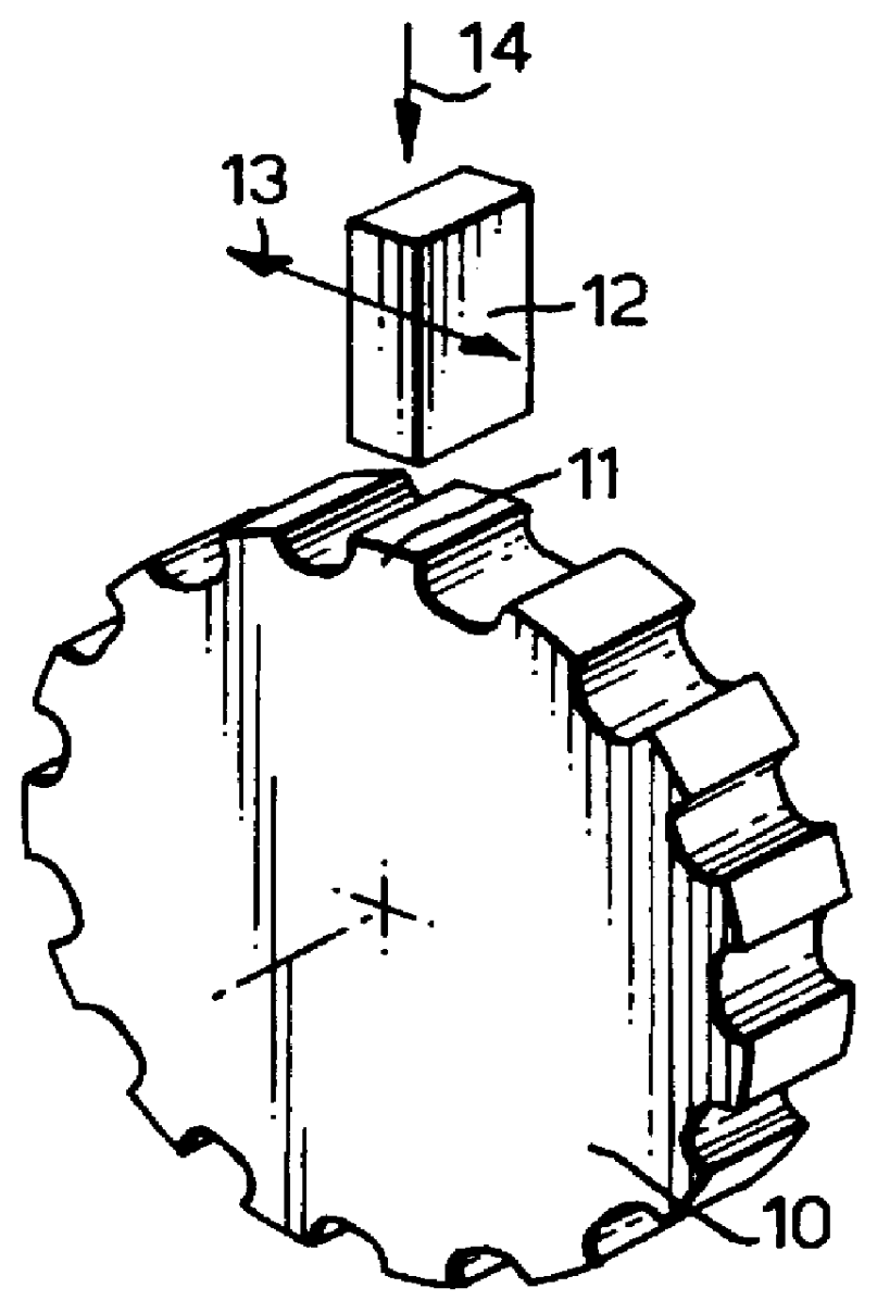
The present invention employs a form of friction welding using linear motion in which the blade is reciprocated in a rectilinear movement in a plane which in the prior art is usually tangential to the disk and applying a forging force in a radial direction. This known process is illustrated in the accompanying FIG. 1 which is a diagrammatic view of a disk 10 and a single blade blank 12. The disk 10 is provided with a plurality of upstanding stubs 11 on its periphery, that is its circumferential surface. Typically, a blade 12 is urged in contact with the stub 11 by a force 14 and oscillated to and fro in the directions of arrows 13 over a range of linear movement in a range from .+-.1 mm to .+-.3 mm. This range of movement is a typical example only and the given dimensions are not intended to be limiting. Simultaneously a suitable forge force 14 is applied in a generally radially inward direction, see arrow 14 in the drawing. The magnitude of the forge force 14 depends on the area of...


PUM

PropertyMeasurementUnit
Forceaaaaaaaaaa
Angleaaaaaaaaaa
Heightaaaaaaaaaa

Abstract

A method of making a BLISK by linear friction welding, comprises providing a stub on the circumferential surface of a turbine disk and defining a weld joint surface on the radially outermost face of the stub. The weld joint surface follows the annulus curvature in axial and circumferential directions while remaining flat in a third direction. A blade is applied radially to the stub and linear friction welding of the blade to the stub is effected by oscillating the blade in said third direction while applying a welding force inwardly along the blade.

Description

1. Field of the InventionThis invention concerns improvements in or relating to the friction welding of components.In particular, the invention concerns a method for the manufacture or repair of a BLISK by linear friction welding.2. Description of the Related ArtThe two most commonly used methods for manufacturing BLISKs are machining from solid and attaching separately made blades onto a disk by friction welding. A further operation to remove upset or welding flash may be required as part of a finish machining procedure. Machining from solid is expensive and inevitably results in an unacceptable wastage of material, especially in the case of larger BLISKs. The method of present interest, in any case, can be employed as a repair technique to replace individual blades irrespective of whether a BLISK was manufactured from solid or fabricated using the same method. However, friction welding of blades onto a disk permits the blade and disk properties to be optimised, such as in a cast b...

Claims


Application Information

Patent Timeline
IPC IPC(8): B23K20/12F01D5/30F01D5/34
CPCB23K20/1205B23K20/129F01D5/34F01D5/3061B23K2201/001Y10T29/49316Y10T29/49318B23K2101/001
Inventor BROWNELL, JOHN BGILLBANKS, PETER JHAWKINS, RICHARD JTHROSSELL, JONATHAN PWILSON, JAMES R
Owner ROLLS ROYCE PLC
Why Eureka
Try Eureka