Health monitoring system

a health monitoring and monitoring system technology, applied in the field of health monitoring, can solve the problem that the checkup may not be effective in helping to detect the onset of an adverse medical condition

Inactive Publication Date: 2000-08-01
THE BRIGHAM & WOMEN S HOSPITAL INC
View PDF49 Cites 479 Cited by
  • Summary
  • Abstract
  • Description
  • Claims
  • Application Information

AI Technical Summary

Benefits of technology

The RAM is divided into three regions: 1) the scratchpad; 2) the warehouse (long-term storage of all but 8-bit EKG data); and 3) the 8-bit EKG data area. As data is received, it is placed in the scratchpad. As time permits, data is read from the scratchpad, processed, and stored in the warehouse or the EKG zone, depending on the data type and size. The MS controller stores data received from the RT controller in the scratchpad in the packetized format in which it was received. When not busy with other tasks, the MS controller processes data temporarily stored in the scratchpad and places it in variable-length fields in the warehouse or fixed-length fields in the EKG zone. The data in the warehouse is tagged using a coding method which identifies the data type with a particular sequence of leading bits. This allows proper reassembling of data as it is read out of memory.

Problems solved by technology

However, unless a patient's checkup is fortuitously scheduled for a time at which symptoms of an ensuing illness are just developing, the checkup may not be effective in helping to detect the onset of an adverse medical condition.

Method used


Image

  • Health monitoring system
  • Health monitoring system
  • Health monitoring system

Examples


Embodiment Construction

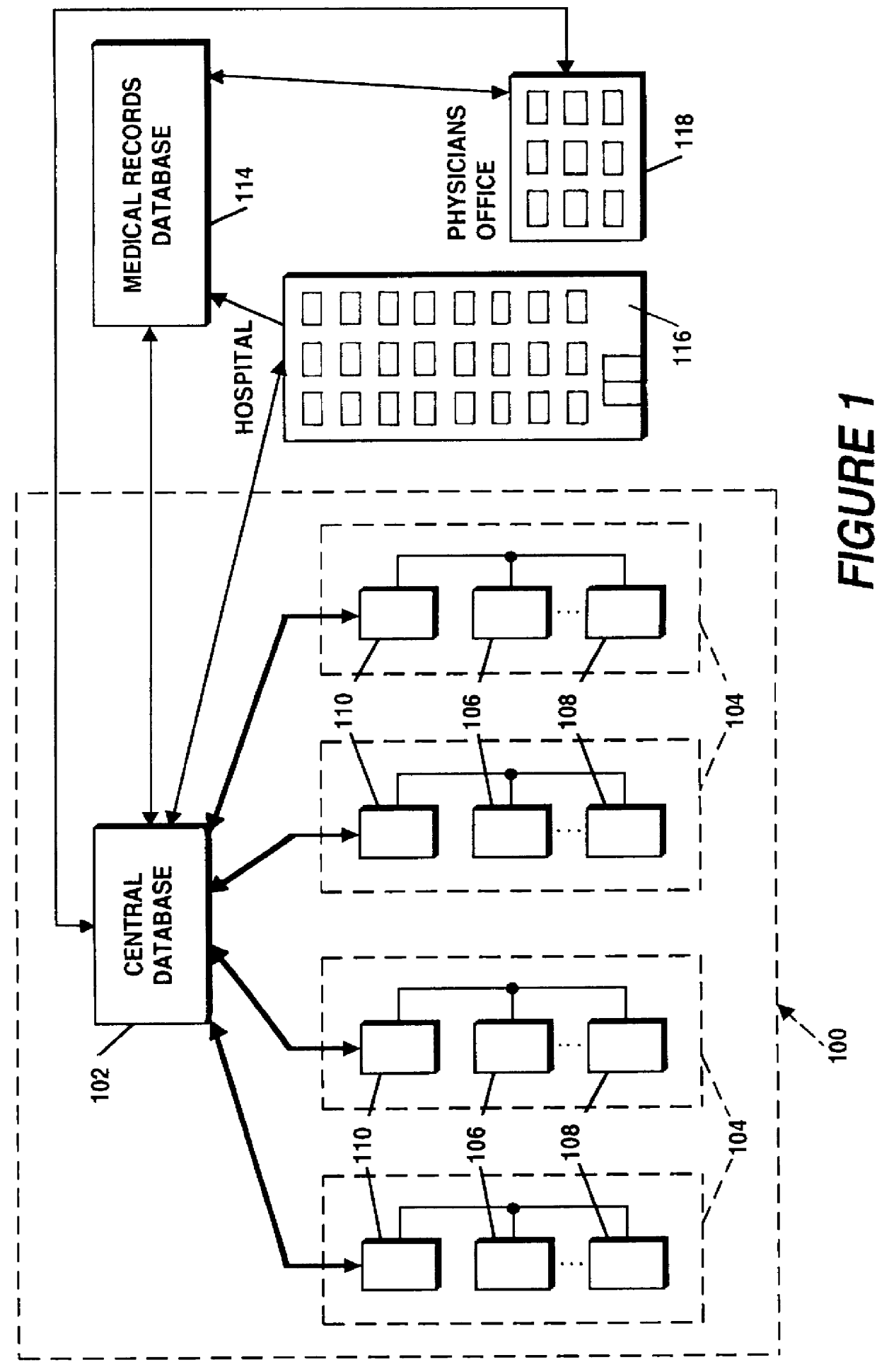
Shown in FIG. 1 is a health tracking system 100 which has a central database 102 with a data link connectable to each of a plurality of health trackers 104. In the preferred embodiment, each of the health trackers 104 includes a multiparametic physiological monitor 108 and a subjective data logger 106. In the preferred embodiment the monitor 108 connects directly to a modem 110 (when used without a data logger 106), or can be connected to a serial data port on the subjective data logger which, in turn, connects to a modem 110. In the preferred embodiment an external modem is used primarily because of lower cost, however those skilled in the art will recognize that it would also be possible to include a single chip modem in the monitor 108 or to plug a PCMCIA modem into the data logger 106. The external modem of the preferred embodiment also includes a chargepad for recharging the batteries of the portable monitor 108 and data logger 106 units.

The monitor 108 and the data logger 106 ...


PUM


Abstract

A health monitoring system which tracks the state of health of a patient and compiles a chronological health history of the patient uses a multiparametric monitor which periodically and automatically measures and records a plurality of physiological data from sensors in contact with the patient's body. The data collected is not specifically related to a particular medical condition but, instead, provides the information necessary to derive patterns which are characteristic of healthy patients as well as those who are ill. The data collected is periodically uploaded to a database in which it is stored along with similar health histories for other patients. The monitor is preferably self-contained in a chest strap which is located on the patient's torso, and makes use of a controller which controls sampling of the desired data and storage of the data to a local memory device pending uploading to the database. The more voluminous data collected is reduced and compressed prior to storage in the local memory device. Preferably, much of the monitor circuitry is run intermittently to conserve power. The monitor data is supplemented with subjective data (such as psychological and environmental conditions) collected from the patient using a handheld data input device which runs a program to solicit information from the patient. The subjective data collected is chronologically aligned with the monitor data in the database such that the health history of a patient includes both objective and subjective medical data.

Description

1. Field of the InventionThe present invention relates to the field of medicine and health and, more specifically, to health tracking including assessing trends in health and the diagnosing and monitoring of medical conditions.2. Description of the Related ArtIn the medical profession today, the advent of high technology has provided a myriad of impressive diagnostic tools. However the focus of this medical technology has been on diagnosis of acute conditions, rather than advanced warnings and preventive advice. Routine "checkups" are the recognized method of monitoring a person's health. Such examinations provide a physician with information relating to the patient's condition. However, unless a patient's checkup is fortuitously scheduled for a time at which symptoms of an ensuing illness are just developing, the checkup may not be effective in helping to detect the onset of an adverse medical condition.Portable health monitors have been developed in the past which monitor body par...

Claims


Application Information

Patent Timeline
Patent Type & Authority Patents(United States)
IPC IPC(8): A61B5/00A61B5/0404A61B5/0402A61B5/11A61B5/113A61B5/332A61B5/366A61B7/00
CPCA61B5/02055A61B5/02405A61B5/0404A61B5/0452A61B5/1135A61B5/4824A61B5/4839A61B5/6831A61B5/6861A61B5/7275A61B5/7475A61M31/002G06F19/322G06F19/3418A61B5/002A61B5/01A61B5/0402A61B5/0472A61B7/00A61B2560/0209A61B2560/0242A61B2560/0257A61B2560/0295A61B5/7232A61B5/7435G16H10/60G16H40/67A61B5/332A61B5/366A61B5/349A61B5/318
Inventor RAYMOND, STEPHEN A.GORDON, GEOFFREY E.SINGER, DANIEL B.
Owner THE BRIGHAM & WOMEN S HOSPITAL INC
Why Eureka
Try Eureka